
Multiconfiguration X-ray Optical System

a multi-configuration, optical system technology, applied in the field of x-ray beam system, can solve the problems of inability to optimize independently, inability to adjust the sensitivity of the x-ray beam,

Active Publication Date: 2011-04-14
RIGAKU INNOVATIVE TECH
View PDF18 Cites 47 Cited by
  • Summary
  • Abstract
  • Description
  • Claims
  • Application Information

AI Technical Summary

Benefits of technology

"The present invention provides an improved x-ray optical system that can produce multiple types of beams with minimal effort and alignment. The system includes an x-ray source, two optical elements, and an optional third element. The first optical element conditions the x-rays to form two collimated beams that can be directed to a sample or a detector. The system can deliver two beams that are not parallel to each other, and can also produce different formalities of beams with minimal effort. The technical effects of this invention are improved flexibility and efficiency in producing multiple types of beams with a minimum of components and effort."

Problems solved by technology

These parameters, however, are typically interdependent and, therefore, cannot be optimized independently.
That is, usually, improving or optimizing one parameter often times results in an unavoidable cost to the other parameters.
Different optical systems are needed for different applications, or the capability of a diffractometer is limited.
Significant effort may be required to change and align an optical component whenever it is installed or changed.
Further, having these various optical systems can be costly.

Method used


Image

  • Multiconfiguration X-ray Optical System
  • Multiconfiguration X-ray Optical System
  • Multiconfiguration X-ray Optical System

Examples


Embodiment Construction

The x-ray beam system disclosed in invention mainly concerns x-ray scattering and x-ray diffraction.

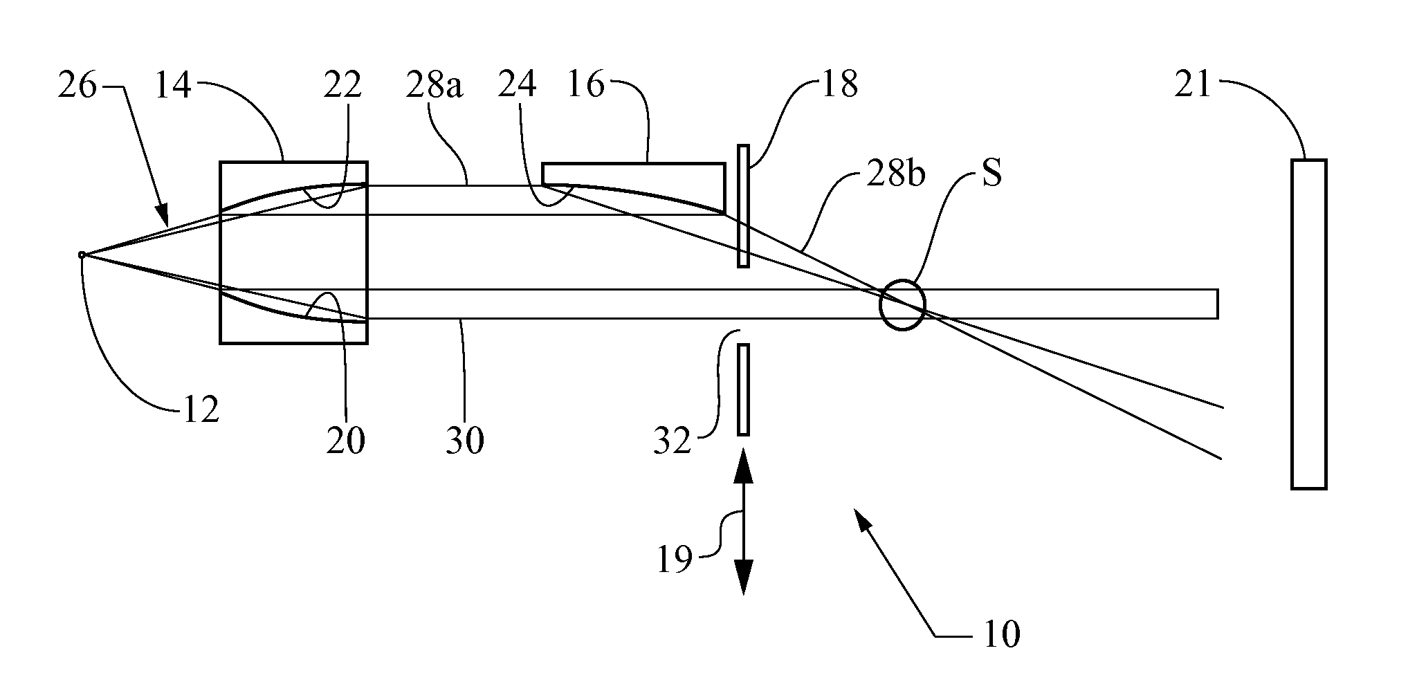
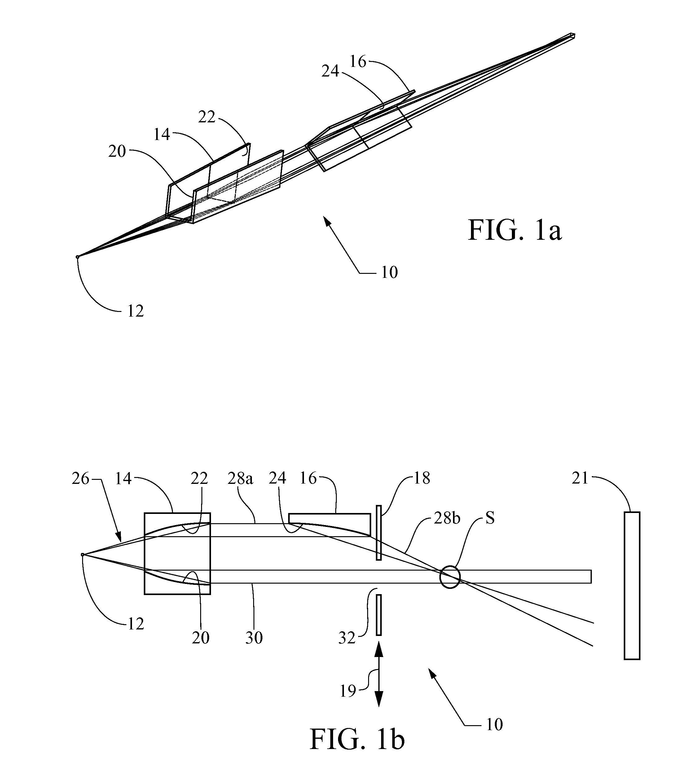
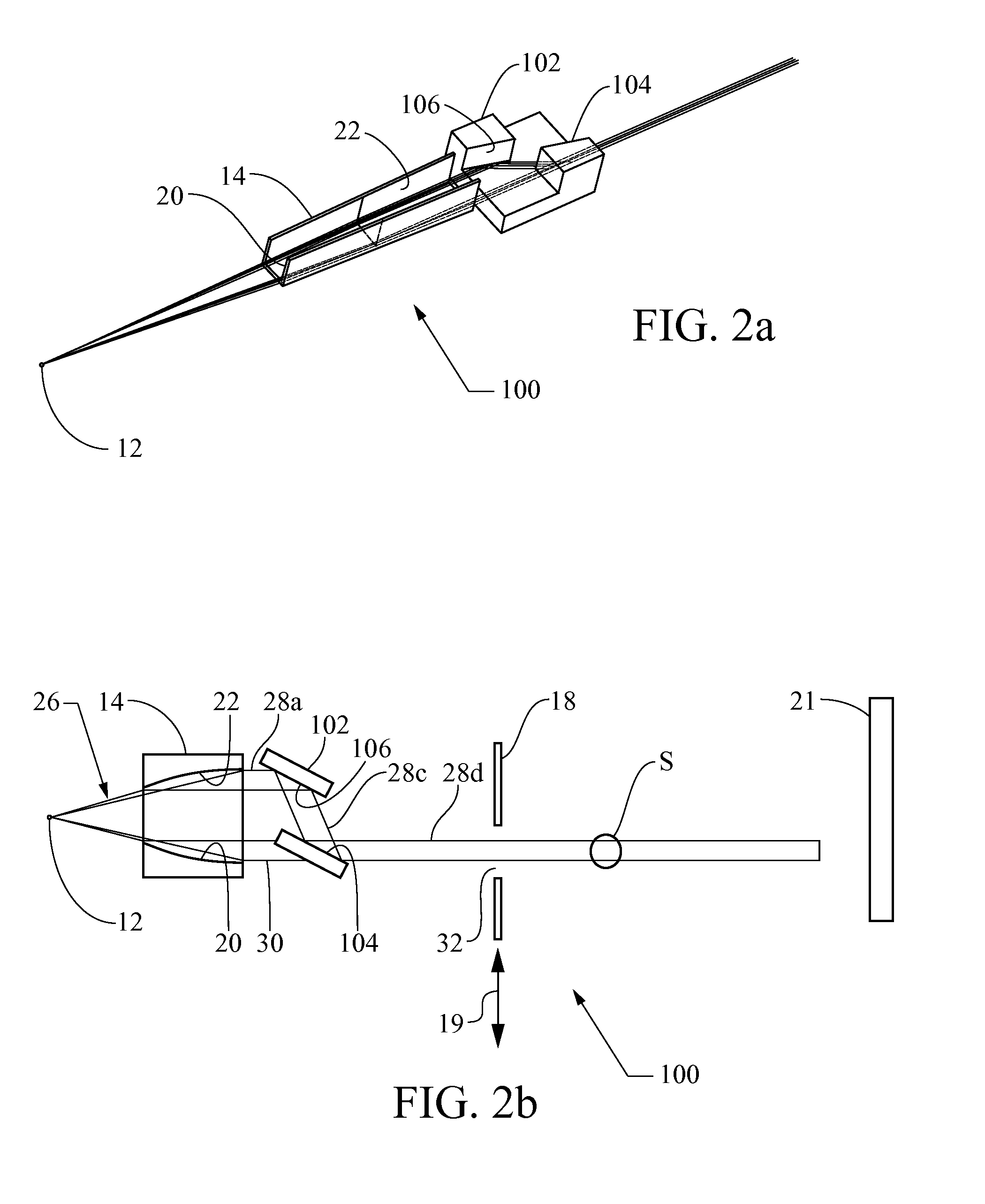
Referring now to FIG. 1a, an x-ray system embodying the principles of the present invention is illustrated therein and designated at 10. As its primary components, the x-ray system 10 includes a source 12, such as, for example a laboratory x-ray source in point geometry or line geometry if the optical system is a one-dimensional system, a first optical element 14, and a second optical element 16. The first optical element 14 delivers two parallel beams and the second optical 16 element further conditions one of the two beams delivered by the first optical element. The first optical element 14 can be a Kirkpatrick-Baez optical system including two optics in which at least one of the two reflection surfaces of each optic is a multilayer reflector. Particularly, the optic in can be a “2-corner” side-by-side optical element, in which two reflectors are facing each other and the third refl...


PUM


Abstract

An x-ray optical system includes an x-ray source which emits x-rays, a first optical element which conditions the x-rays to form two beams and at least a second optical element which further conditions at least one of the two beams from the first optical element.

Description

BACKGROUNDThe present invention relates generally to an x-ray beam system.There are various applications which utilize conditioned beams, which include, but are not limited to, directed, monochromatized, collimated or focused x-rays. For example, medical radiotherapy systems utilize x-rays to destroy malignant tissue, x-ray diffraction or scattering analysis systems channel x-ray radiation at a sample, crystal or non-crystal, to generate a diffraction or scattering pattern corresponding to its structure, and x-ray fluorescence and spectroscopy systems employ an x-ray beam to generate secondary radiation and analyze the secondary radiation to obtain compositional information.In the field of x-ray diffraction, an x-ray instrument, such as a diffractometer, employs an x-ray beam conditioned by an optical system to meet certain requirements, including spatial definition (such as parallelism), spectrum purity, and intensity, as well as other requirements. These parameters, however, are t...

Claims


Application Information

Patent Timeline
Patent Type & Authority Applications(United States)
IPC IPC(8): G21K1/02
CPCB82Y10/00G21K1/06G21K2201/064G21K2201/062G21K2201/061
Inventor VERMAN, BORISPLATONOV, YURIYJIANG, LICAI
Owner RIGAKU INNOVATIVE TECH
Learn More