Method for thermally compensating a gaging device and thermally compensated gaging station

a gaging device and thermal compensation technology, applied in the direction of calibration apparatus, instruments, using mechanical means, etc., can solve the problems of environmental temperature, inability to obtain a gaging device, and affect the information provided by a gaging device such as a position sensor, so as to achieve the effect of convenient and cheap implementation

Inactive Publication Date: 2011-03-31
MARPOSS SPA
View PDF13 Cites 1 Cited by
  • Summary
  • Abstract
  • Description
  • Claims
  • Application Information

AI Technical Summary

Benefits of technology

[0005]Object of the present invention is to provide a method for thermally compensating a gaging device and a thermally compensated gaging station, which method and station do not present the above described disadvantages and can be easily and cheaply implemented.

Problems solved by technology

The information provided by a gaging device such as a position sensor is affected, among other things, by the environmental temperature, since a temperature variation causes so-called thermal drifts caused by both unavoidable thermal deformations in the metal component parts of the position sensor, and unavoidable variations in the electrical resistance of the electric circuits of the position sensor.
However, it is not possible to obtain a gaging device which be totally insensitive to the effects of the temperature variations.
However, the known methods (for example of the same type as the one described in patent US5689447A1) for determining the value of the thermal compensation coefficient involve quite remarkable approximations, and thus they do not enable to achieve a very accurate compensation.
As a consequence, the known methods can not be applied to gaging applications requiring an extremely high accuracy.

Method used


Image

  • Method for thermally compensating a gaging device and thermally compensated gaging station
  • Method for thermally compensating a gaging device and thermally compensated gaging station
  • Method for thermally compensating a gaging device and thermally compensated gaging station

Examples


Embodiment Construction

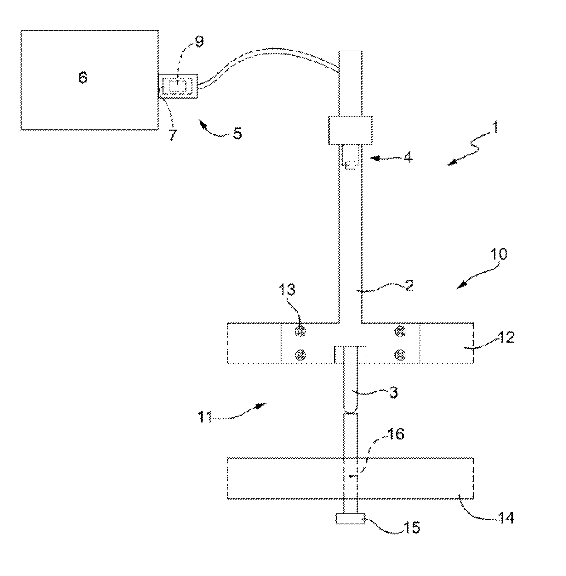
[0012]In FIG. 1, the reference number 1 indicates, on the whole, a gaging device, e.g. a position sensor including a linear transducer of the LVDT (Linear Variable Differential Transformer) type, for instance of the same type as the one described in US patent US6931749B1. The gaging device or position sensor 1 includes a stationary part 2 and a movable element, more specifically a slider 3, which carries a feeler and is movable with respect to the stationary part. The transducer of the position sensor 1 includes windings and a movable core (per se known and thus not illustrated in the attached sheets of drawings), connected to the stationary part 2 and to the movable element or slider 3, respectively, and is adapted for providing an alternating electrical signal which has a variable intensity voltage and depends on the position of the movable slider 3. The windings of the transducer of the position sensor 1 are part of an electric circuit which is schematically shown in FIG. 1 with ...


PUM


Abstract

Thermal drifts compensation method in a gaging device (1) with a transducer; the compensation method includes the steps of: determining and storing, in the course of a calibration operation, values of a thermal compensation coefficient (K) upon variation of a temperature (T) of the gaging device (1); detecting, in the course of a gaging operation, a current reading (X) of the gaging device (1); detecting, in the course of the gaging operation, a current temperature (T) of the gaging device (1); determining, in the course of the gaging operation, the current value of the thermal compensation coefficient (K) by means of the values of the thermal compensation coefficient (K) previously determined and stored in the course of the calibration operation as a function of both the current temperature (T) of the gaging device (1) and the current reading (X) of the gaging device (1); and correcting, in the course of the gaging operation, the current reading (X) of the gaging device (1) by means of the current value of the thermal compensation coefficient (K).

Description

TECHNICAL FIELD[0001]The present invention relates to a method for thermally compensating a gaging device, and to a thermally compensated gaging station.BACKGROUND ART[0002]The information provided by a gaging device such as a position sensor is affected, among other things, by the environmental temperature, since a temperature variation causes so-called thermal drifts caused by both unavoidable thermal deformations in the metal component parts of the position sensor, and unavoidable variations in the electrical resistance of the electric circuits of the position sensor. For attempting to render the sensor less sensitive to the temperature variations, the position sensor can be implemented with materials having limited thermal deformations and limited electrical resistance variations. However, it is not possible to obtain a gaging device which be totally insensitive to the effects of the temperature variations.[0003]In the high accuracy gaging devices and sensors it is known to carr...

Claims


Application Information

Patent Timeline
Patent Type & Authority Applications(United States)
IPC IPC(8): G06F19/00G12B13/00G12B7/00
CPCG01D5/42G01D18/00
Inventor ZANETTI, BRUNOALDROVANDI, MATTEOMONTANARI, WILLIAM
Owner MARPOSS SPA
Why Eureka
Try Eureka