Differential signal transmission system and method

Inactive Publication Date: 2011-03-31
FUJITSU LTD
View PDF36 Cites 14 Cited by
  • Summary
  • Abstract
  • Description
  • Claims
  • Application Information

AI Technical Summary

Problems solved by technology

The higher the bit rate, the more severe the waveform distortion of a transmission signal becomes.
As a result, a margin of the time delay difference between the differential signals is reduced, and it is difficult to receive correctly a data signal.
If the delay time difference is large between the transmission paths for transferring the differential signals in the above-described related art, it is difficult to maintain a differential state between the differential signals received by the receiver.
It is thus difficult to detect the skew (phase difference) of the differential signals.
The compensation for the skew of the differential signals is thus difficult, and an erratic operation may take place in a subsequent circuit of the receiver.

Method used


Image

  • Differential signal transmission system and method
  • Differential signal transmission system and method
  • Differential signal transmission system and method

Examples


first embodiment

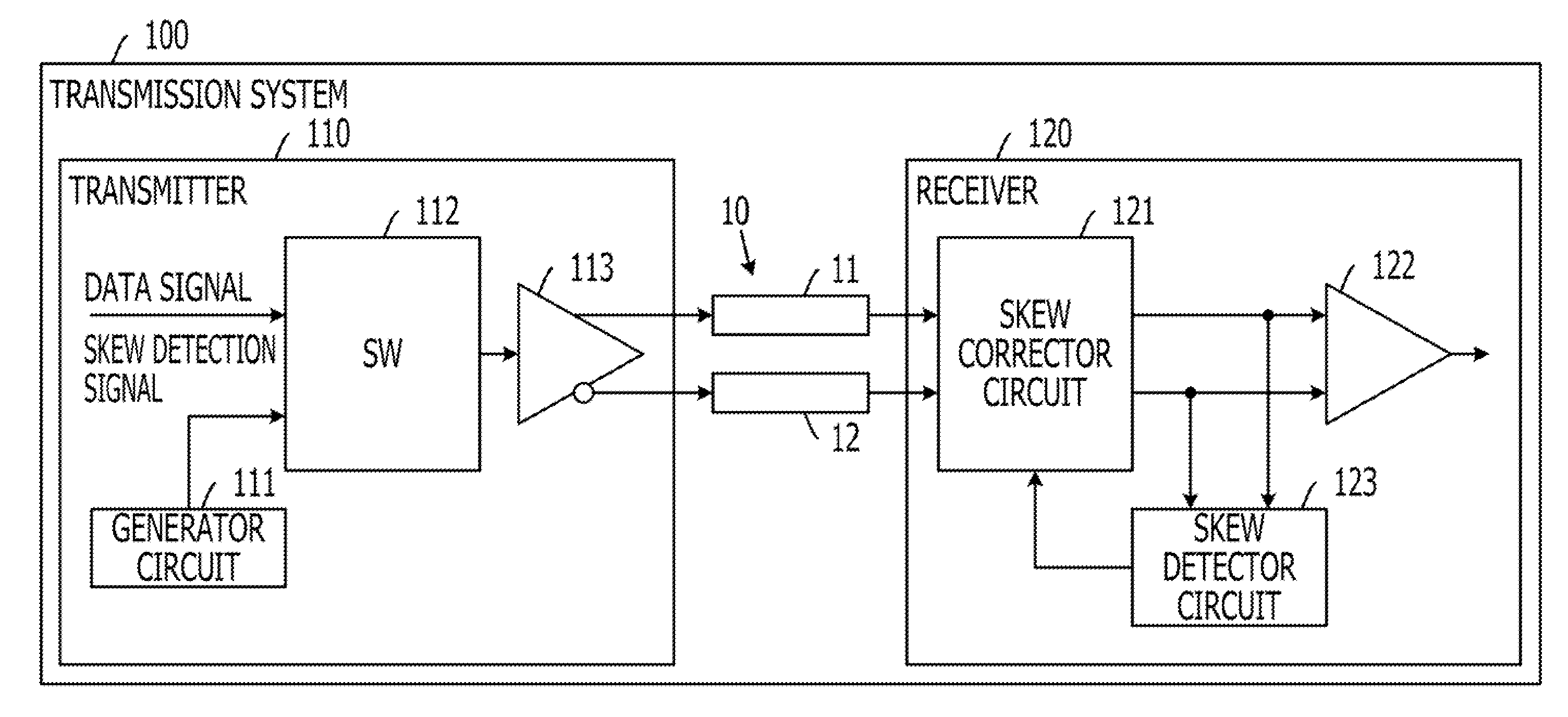
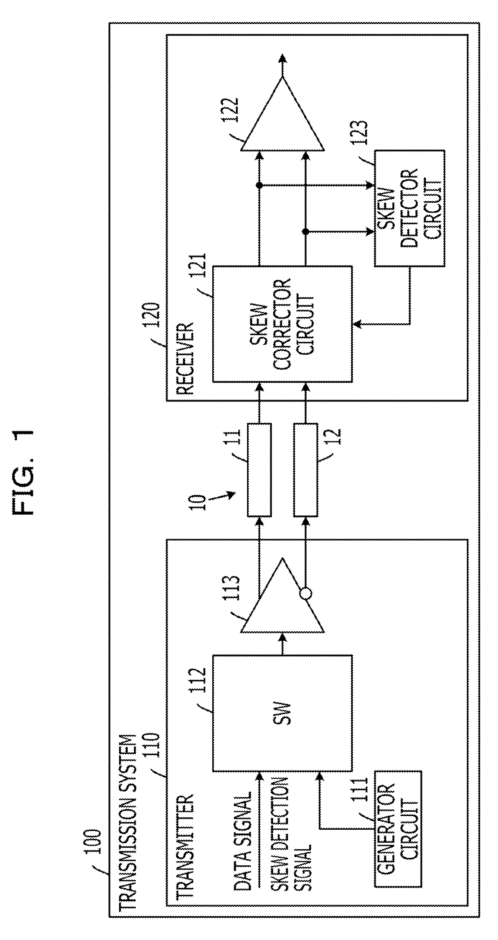
[0036]FIG. 1 is a block diagram illustrating an exemplary transmission system of a first embodiment. Referring to FIG. 1, a transmission system 100 of the first embodiment includes a transmission line 10, a transmitter 110, and a receiver 120. The transmission system 100 transmits a data signal (first differential signal) from the transmitter 110 to the receiver 120 via the transmission path 10. The transmission system 100 is an information processing apparatus such as a server system.

[0037]The transmission line 10 is a transmission path that permits the differential signals (electrical signal) to transfer therethrough. The transmission line 10 includes a positive-side transmission path 11 for transferring a positive-side signal of the differential signals and a negative-side transmission path 12 for transferring a negative-side signal of the differential signals. The transmission path 10 is preferably constructed such that the positive-side transmission path 11 and the negative-sid...

second embodiment

[0065]FIG. 8 is a block diagram illustrating an exemplary structure of a transmission system 100 of a second embodiment. Referring to FIG. 8, elements that may be substantially identical to those illustrated in FIG. 1 are designated with the same reference numerals, and the discussion thereof is omitted here. As illustrated in FIG. 8, the receiver 120 in the transmission system 100 includes a signal ditector circuit 821 in addition to the arrangement illustrated in FIG. 1.

[0066]The signal sensor circuit 821 senses the skew detection signal output by the transmitter 110. More specifically, the signal sensor circuit 821 acquires the differential signal output from the skew corrector circuit 121 to the differential circuit 122, and determines whether the acquired differential signal is a skew detection signal. If the acquired differential signal is a skew detection signal, the signal sensor circuit 821 outputs a sense signal to the skew detector circuit 123.

[0067]The signal sensor circ...

third embodiment

[0077]FIG. 11 is a block diagram illustrating an exemplary structure of a transmission system 100 of a third embodiment. Referring to FIG. 11, elements that may be substantially identical to those illustrated in FIG. 1 are designated with the same reference numerals and the discussion thereof is omitted here. Referring to FIG. 11, the transmission system 100 of the third embodiment includes a control circuit 1110 in addition to the structure of FIG. 1. The control circuit 1110 may be a processing circuit such as a digital signal processor (DSP). The control circuit 1110 may output concurrently a correction command to the transmitter 110 and the receiver 120 at the time of power-on or resetting of the transmitter 110, or at the time at which a user enters a command.

[0078]If no correction command is output from the control circuit 1110, the switch 112 in the transmitter 110 outputs the data signal. If a correction command is output from the control circuit 1110, the switch 112 in the ...


PUM


Abstract

A transmission system for transmitting a first differential signal includes a transmitter, a transmission path, and a receiver. The transmitter transmits the first differential signal and a second differential signal. The transmission path transfers the first differential signal and the second differential signal. The receiver receives the first differential signal and the second differential signal. The transmitter includes a generator circuit and a switch. The generator circuit generates the second differential signal lower in baud rate than the first differential signal. The switch selects between the second differential signal and the first differential signal to output the selected differential signal to the transmission path. The receiver includes a detector circuit and a corrector circuit. The detector circuit detects a skew of the second differential signal. The corrector circuit corrects a skew of the first differential signal based by the detected skew of the second differential signal.

Description

CROSS-REFERENCE TO RELATED APPLICATIONS[0001]This application is based upon and claims the benefit of priority of the prior Japanese Patent Application No. 2009-222396, filed on Sep. 28, 2009, the entire contents of which are incorporated herein by reference.FIELD[0002]The present invention relates to a transmission system and method of transmitting a differential signal.BACKGROUND[0003]A bit rate (speed) between boards is increased in an information processing apparatus such as a server system as a processing speed of a central processing unit (CPU) increases. A differential signal, having advantages such as noise immunity or low radiation of electro-magnetic interference (EMI), is used in the information processing apparatus that exchanges an electrical signal at a high-speed communication (Refer to Japanese Laid-open Patent Publication No. 10-303708).[0004]Differential signals include two signals, i.e., a positive-side signal and a negative-side signal. Depending on variations in...

Claims


Application Information

Patent Timeline
IPC IPC(8): H04L25/49H04L27/00
CPCH04L25/14H04L25/0272
Inventor KUWATA, NAOKI
Owner FUJITSU LTD
Why Eureka
Try Eureka