
Masonry bracket, system and construction method

Inactive Publication Date: 2011-03-31
WEMBLEY INNOVATION
View PDF27 Cites 14 Cited by
  • Summary
  • Abstract
  • Description
  • Claims
  • Application Information

AI Technical Summary

Benefits of technology

[0009]The present invention provides a masonry wall reinforcing bracket comprising an elongate inter-course stress transfer member, the stress transfer member comprising a rebar cradling feature. The stress transfer member may comprise a plate operative to be located withi

Problems solved by technology

Larger spans of masonry wall between the load-bearing columns, or walls with openings (e.g. for doors or windows) are more susceptible to forces perpendicular to the plane of the wall such as those exerted by wind.
Excessive forces may cause failures in the structural integrity of the wall which can result in cracking or failure.
Windposts are typically large and cumbersome in nature making them difficult to install.
Because of their cumbersome nature, windposts are also difficult to handle and are not desirable from a health and safety standpoint, where good practice and / or regulations require that building components carried by hand be of particular maximum manageable weights, typically 20 kg or less.
Windposts are also expensive, have significant procurement lead in times, and after installation, quite often require further treatment to enhance their aesthetic, fire resistance, thermal insulation and / or acoustic properties.
However this is more labour intensive and time consuming than casting the bond beam in a single pour.
It may also introduce structural weaknesses into the bond beam if the separately cast sections do not fully knit together, or the rebar is moved laterally whilst the next layer of concrete is being placed and vibrated.

Method used


Image

  • Masonry bracket, system and construction method
  • Masonry bracket, system and construction method
  • Masonry bracket, system and construction method

Examples


Embodiment Construction

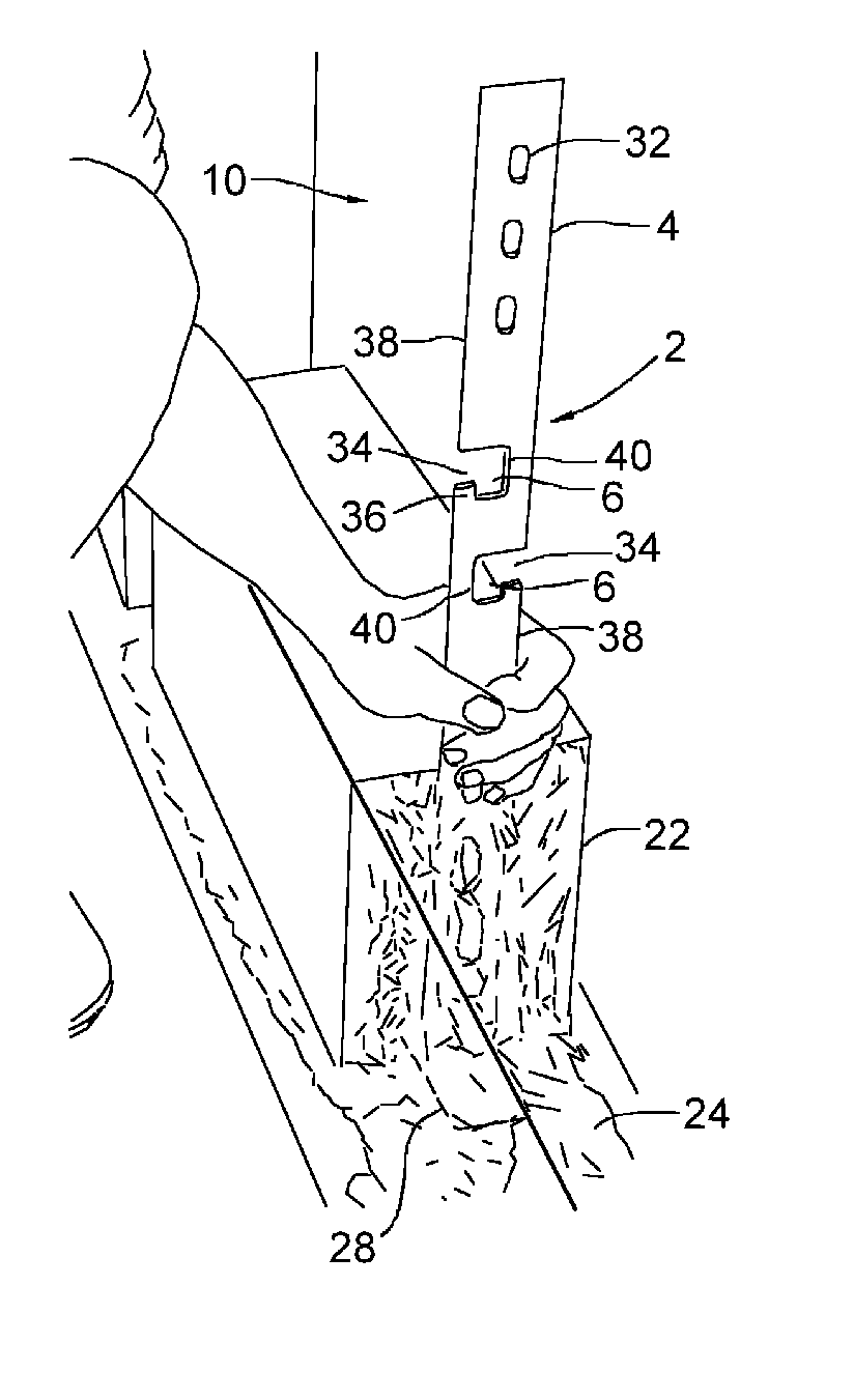
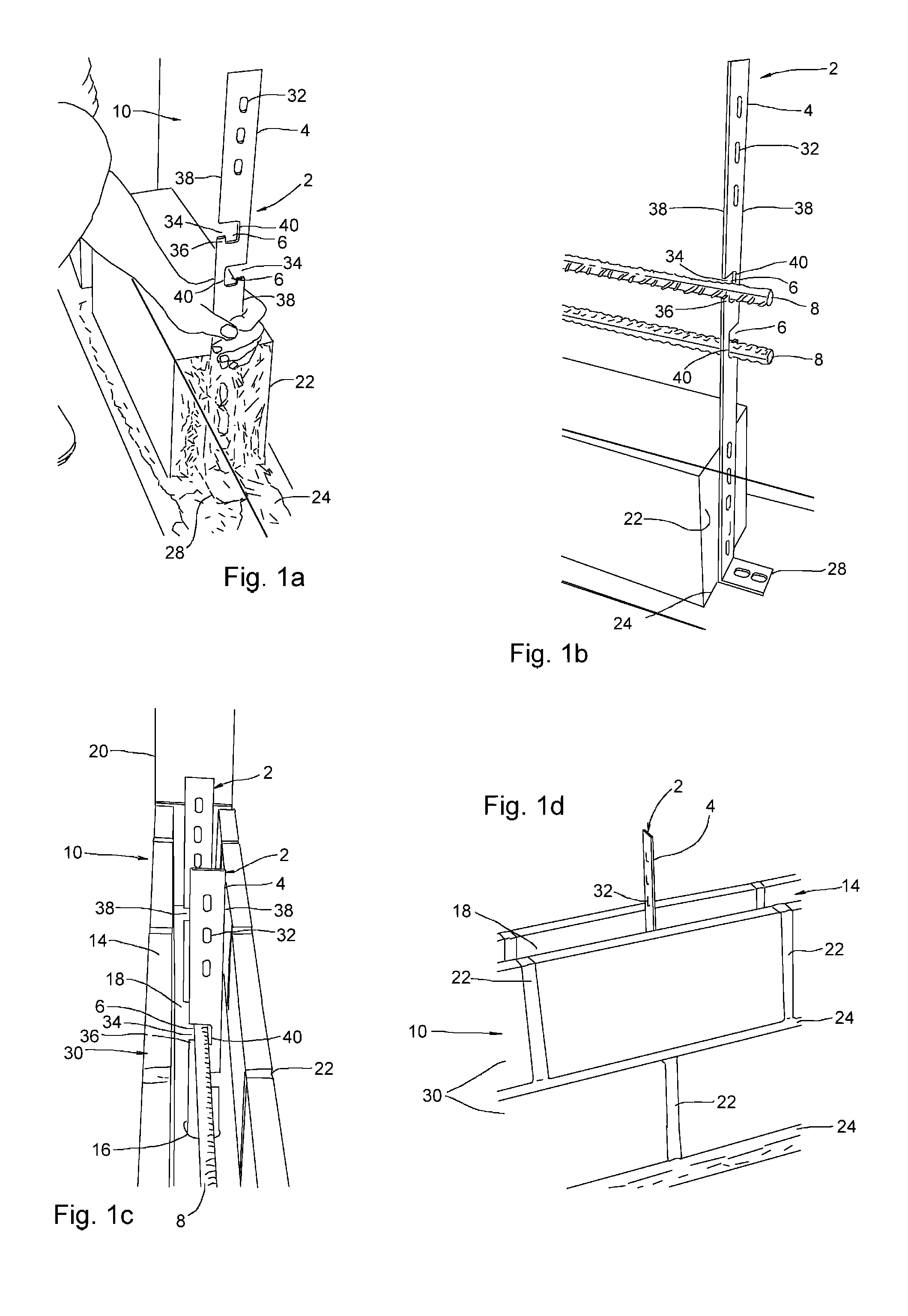
[0024]Referring to FIGS. 1a-1e, the present invention provides a masonry wall reinforcing bracket 2 comprising an elongate stress transfer member 4 adapted and configured to extend between at least two courses 30 of masonry in use. The stress transfer member 4 further comprises one or more rebar cradling features 6. The cradling feature 6 is operative to support and locate a rebar 8 within a masonry wall 10, e.g. to allow it to be cast into a bond beam 12 formed within a course of hollowed masonry units 14. The bracket 2 is formed from a material that is stronger in tension and shear compared to the bond beam matrix material (i.e. concrete, usually) and mortar. Such a bracket 2 material could be steel or another metal, or a metallic or non metallic composite material.

[0025]As shown, the stress transfer member 4 extends between at least two immediately adjacent masonry courses 30, but it may in principle extend through any number of masonry courses 30. In use the stress transfer memb...


PUM


Abstract

The present invention provides a masonry wall reinforcing bracket (2) comprising an elongate inter-course shear transfer member (4), the shear transfer member (4) comprising a rebar cradling feature (6). The shear transfer member (4) may further comprise a plate (5) operative to be located within at least a perpend (22) of a masonry wall (10). The bracket may further comprise a supporting member (28) that protrudes perpendicularly from the length of the shear transfer member (4). The supporting member (28) may comprises a plate operative to be located within a bed joint (24) of the masonry wall (10). The supporting member (28) may be a stabilising foot. The rebars and brackets are used in a bond beam (10) system incorporated within the wall (10).

Description

FIELD OF THE INVENTION[0001]The present invention concerns reinforcing devices for masonry walls. In particular, the reinforcing devices are brackets transferring stress such as shear forces between masonry courses. The brackets in the present invention are intended to be used in masonry walls comprising reinforcement.RELATED ART[0002]In large buildings, masonry block walls are typically used as an infill for a load bearing framework. The load-bearing framework generally comprises a number of load-bearing steel and / or concrete columns and beams, between which panels of masonry blockwork are formed. Larger spans of masonry wall between the load-bearing columns, or walls with openings (e.g. for doors or windows) are more susceptible to forces perpendicular to the plane of the wall such as those exerted by wind. Excessive forces may cause failures in the structural integrity of the wall which can result in cracking or failure.[0003]It is therefore desirable to introduce reinforcing ele...

Claims


Application Information

Patent Timeline
IPC IPC(8): E04B2/16E04B2/84E04B2/02E04C5/01
CPCE04C5/168E04C5/0645E04B2/24E04C5/01E04C5/18
Inventor CLEAR, LIAMCORBETT, HAMISH
Owner WEMBLEY INNOVATION
Learn More