Connector

a technology of connecting parts and contacts, applied in the direction of securing/insulating coupling contact members, coupling device connections, printed circuits, etc., can solve the problems of deformation of the contact stability of the contact parts, and achieve the effect of preventing the contact force and the amount of deformation of the contact parts

Inactive Publication Date: 2011-03-17
JAPAN AVIATION ELECTRONICS IND LTD
View PDF5 Cites 23 Cited by
  • Summary
  • Abstract
  • Description
  • Claims
  • Application Information

AI Technical Summary

Benefits of technology

[0009]The present invention has been made in view of these circumstances, and an object thereof is to provide a connector which makes it possible to accommodate a positional displacement of the connector from a mating connector, and prevent the contact force and the amount of deformation of its contacts from becoming too large.
[0011]With the arrangement of the connector according to the present invention, when the movable-side housing is fitted to the mating connector, the movable-side housing is allowed to be slid in the direction which is orthogonal to the fitting / removing direction, so that the movable-side contact can be pivoted about the pivotal axis which is orthogonal to the fitting / removing direction and the sliding direction of the movable-side housing, and hence the movable-side contact is hardly deformed, and the contact force of the first and second contact portions which are brought into contact with the fixed-side contact and the mating contact, respectively, is prevented from becoming too large.
[0015]According to this invention, it is possible to accommodate the displacement from the mating connector, and prevent the contact force and the amount of deformation of the contacts from becoming too large.

Problems solved by technology

Therefore, there are fears that operating force required in fitting the connector to the card board becomes large, and that the first and second contact portions and the floating portion are plastically deformed, causing degraded contact stability of the contact portions.

Method used


Image

  • Connector
  • Connector
  • Connector

Examples


Embodiment Construction

[0029]The present invention will now be described in detail with reference to the drawings showing preferred embodiments thereof. A description will be given of a connector according to an embodiment of the present invention with reference to FIGS. 1 to 12.

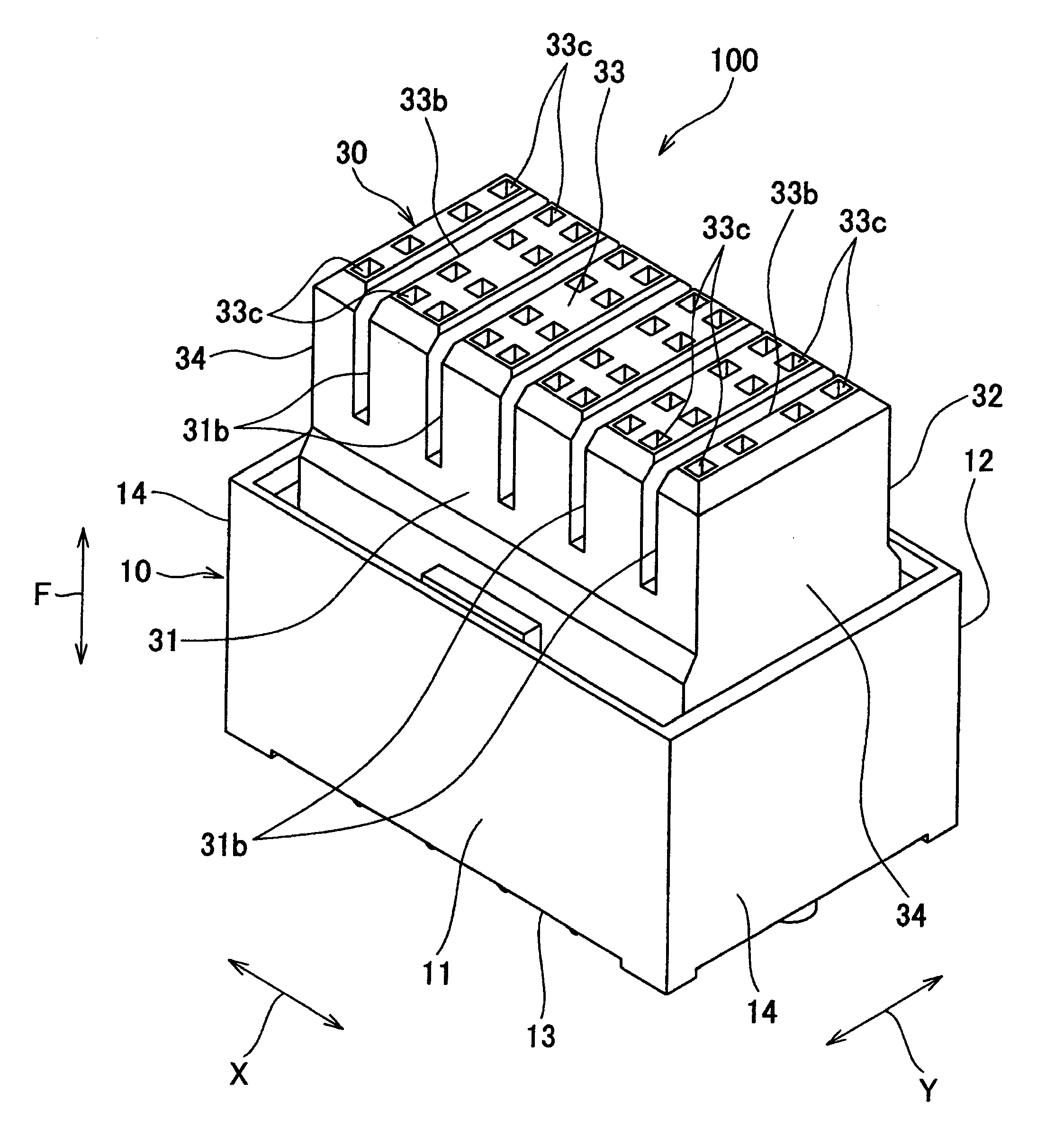
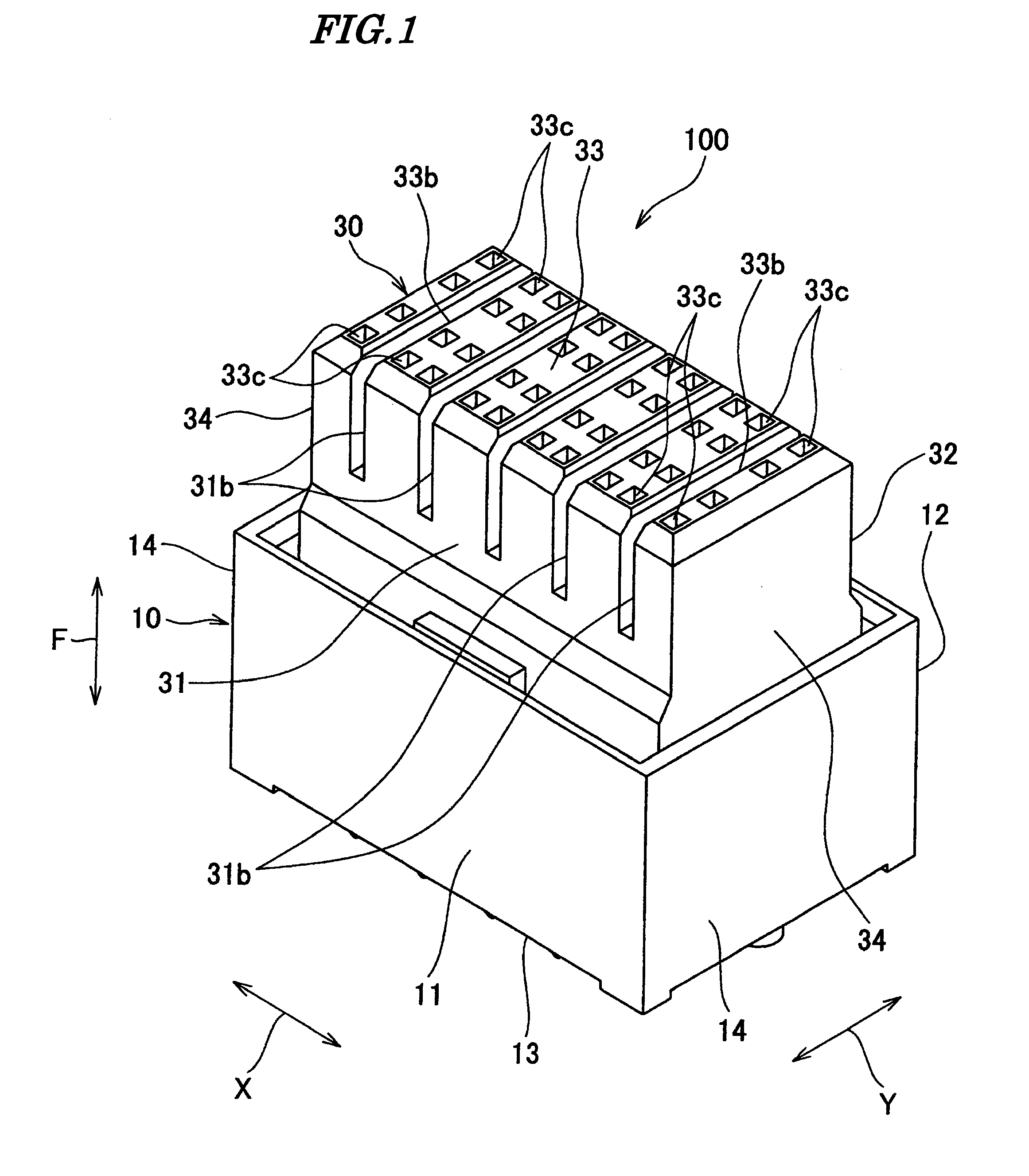
[0030]As shown in FIGS. 1 and 2, a connector 100 comprises a fixed-side housing 10, a plurality of fixed-side contacts 20, a movable-side housing 30, and a plurality of movable-side contacts 40. The connector 100 is mounted on a printed circuit board, not shown, and is capable of being fitted and removed to and from a mating connector 900 (see FIG. 3).

[0031]As shown in FIGS. 1, 2, 5, and 12, the fixed-side housing 10 is box-shaped, and an upper part thereof (upper part of the fixed-side housing 10 as viewed in FIG. 2) is open. The fixed-side housing 10 is integrally formed of insulating resin. The fixed-side housing 10 includes a front portion 11, a rear portion 12, a bottom portion 13, and side portions 14 and 14.

[0032]The front ...


PUM


Abstract

A connector which makes it possible to accommodate positional displacement from a mating connector, and prevent the contact force and the amount of deformation of contacts from becoming too large. Fixed-side contacts are fixed to a fixed-side housings. A movable-side housing is assembled to the fixed-side housing slidably in a direction orthogonal to a fitting / removing direction in which the movable-side housing is fitted to and removed from the mating connector. Movable-side contacts each include first contact portions brought into contact with an associated one of the fixed-side contacts, and second contact portions brought into contact with an associated one of mating contacts of the mating connector. Contact-accommodating chambers for accommodating the movable-side contacts are formed in the movable-side housing such that each movable-side contact can be pivoted about a pivotal axis extending orthogonal to the fitting / removing direction.

Description

BACKGROUND OF THE INVENTION[0001]1. Field of the Invention[0002]This invention relates to a connector that is interposed between two objects to be connected, and electrically connects those objects to be connected to each other.[0003]2. Description of the Related Art[0004]Conventionally, there has been proposed a connector comprising a plurality of contacts, a first and second housing which hold these contacts (see Japanese Laid-Open Patent Publication (Kokai) No. 2008-198441: Paragraphs 0032, 0035, 0036, 0050, and 0051, and FIGS. 9 to 13).[0005]The plurality of contacts are arranged in two rows, upper and lower, and the contacts in the upper row and the contacts in the lower row are arranged in a line-symmetric manner.[0006]The plurality of contacts each include a first and second contact portion, a first and second spring portion, a first and second holding portion, and a floating portion.[0007]When a card board and a motherboard are electrically connected to each other by using t...

Claims


Application Information

Patent Timeline
Patent Type & Authority Applications(United States)
IPC IPC(8): H01R13/40
CPCH01R12/73H01R13/6315H01R13/514H01R13/113
Inventor TAKAGI, OSAMUHASHIGUCHI, OSAMU
Owner JAPAN AVIATION ELECTRONICS IND LTD
Why Eureka
Try Eureka