
Antennas and methods to provide adaptable omnidirectional ground nulls

a technology of omnidirectional ground nulls and antennas, applied in the direction of differential interaction antenna combinations, antenna adaptation in movable bodies, antennas, etc., can solve the problems of large and complex antenna systems of the general publi

Active Publication Date: 2011-03-17
BAE SYST INFORMATION & ELECTRONICS SYST INTERGRATION INC
View PDF5 Cites 20 Cited by
  • Summary
  • Abstract
  • Description
  • Claims
  • Application Information

AI Technical Summary

Benefits of technology

[0022](c) providing a signal representative of the second signal adaptively modified to reduce the amplitude of the output signal provided in step (d), thereby adaptively adjusting the omnidirectional elevation null characteristic.

Problems solved by technology

While providing elevation nulling capabilities, such antenna systems are generally larger and more complex than would typically be appropriate for mounting on a moving truck or other vehicle.

Method used


Image

  • Antennas and methods to provide adaptable omnidirectional ground nulls
  • Antennas and methods to provide adaptable omnidirectional ground nulls
  • Antennas and methods to provide adaptable omnidirectional ground nulls

Examples


Embodiment Construction

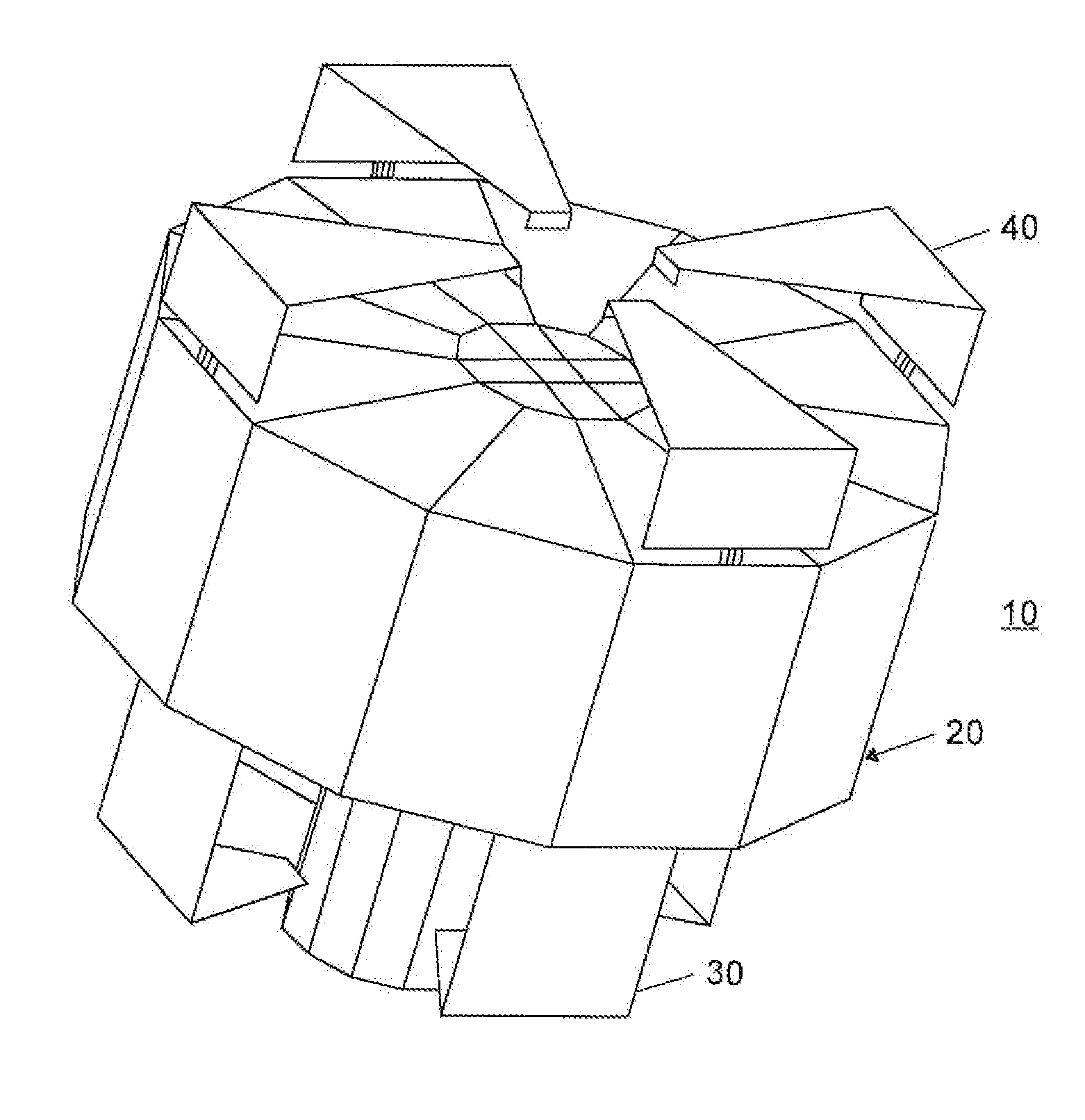
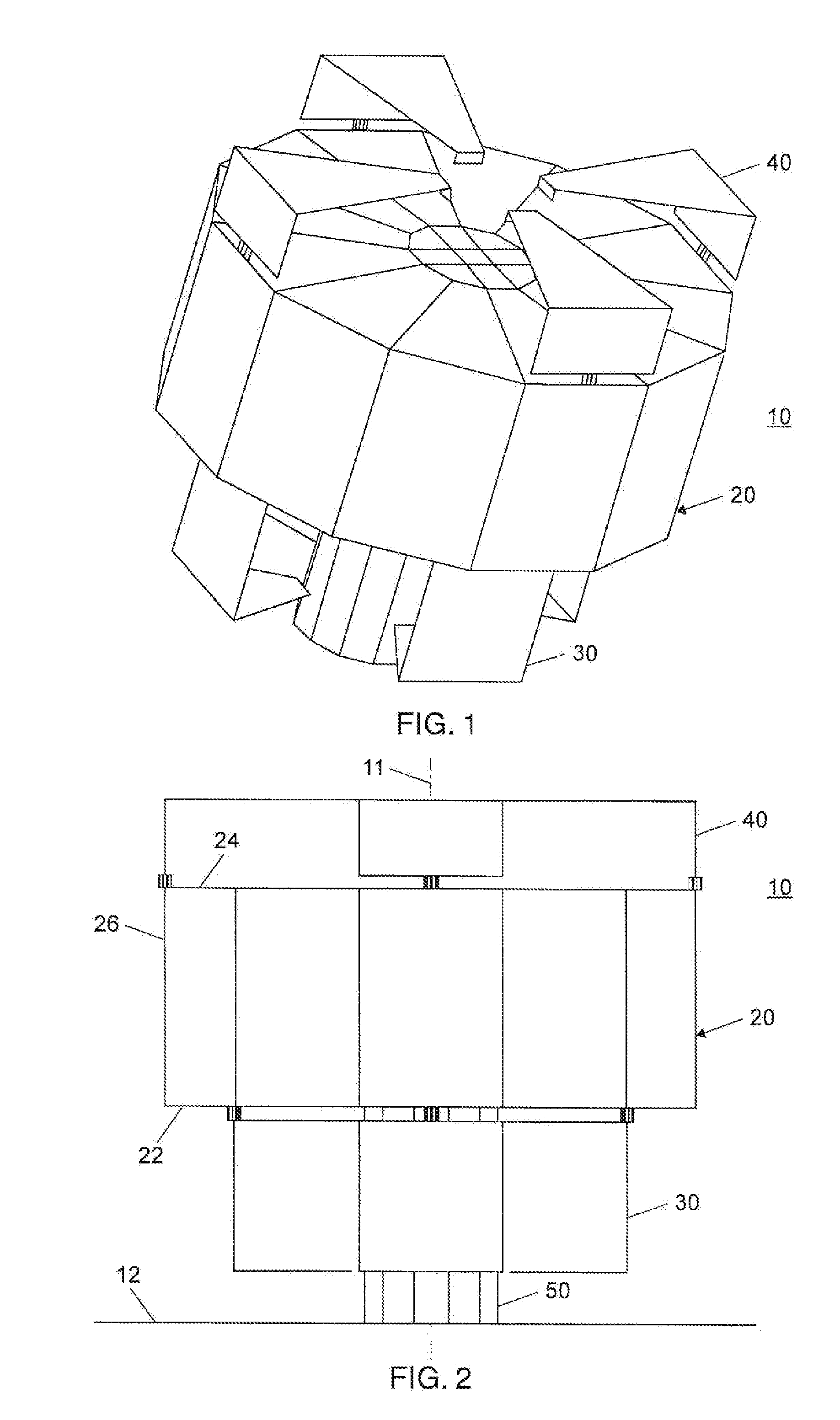
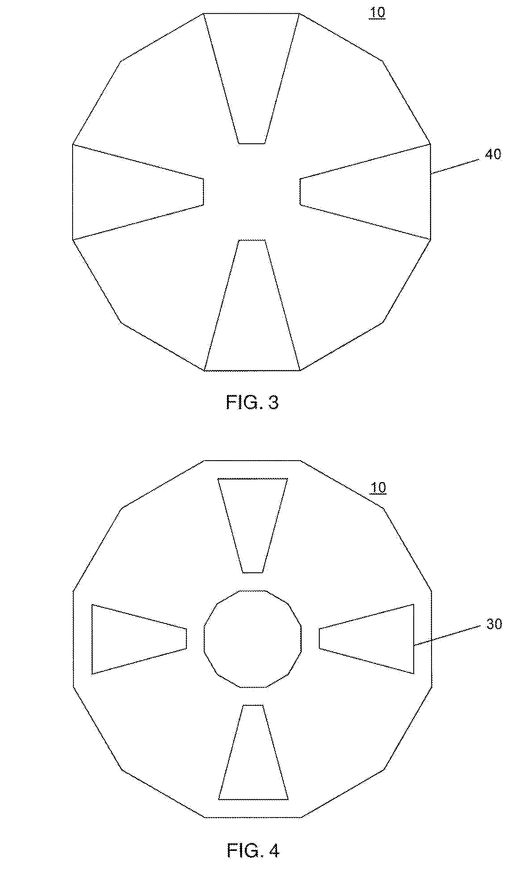
[0034]FIGS. 1, 2, 3 and 4 are respectively a perspective view and side, top and bottom views of an antenna 10 in accordance with a presently preferred embodiment of the invention. As will be described further, this embodiment is configured to provide a reference antenna pattern with a near constant gain over the upper hemisphere and also provide an antenna pattern having an omnidirectional elevation null (i.e., a ground null) characteristic, which may be arranged to be adaptively adjusted. The latter pattern is provided by combinational use of an auxiliary pattern having a distinctive low elevation phase reversal characteristic.

[0035]In this embodiment, antenna 10 has a center axis 11 and includes a cylindrical first structure 20, a first bottom array of four bottom radiating elements, of which element 30 is typical, a second top array of four top radiating elements, of which element40 is typical, and a cylindrical second structure 50. In use, the antenna is preferably positioned ab...


PUM


Abstract

GPS reception on helicopters and ground vehicles may be subject to varying near-ground interference. A compact antenna includes vertically spaced arrays of radiating elements. The first array provides a basic reception pattern. The second array provides a pattern having a distinctive low elevation angle phase reversal. By combining signals for these patterns an antenna pattern with a low angle onmidirectional elevation null characteristic is provided to suppress near-ground interference. Prior to combining, signals from the second array may be modified in amplitude or phase, or both, on a semi-permanent basis, or may be adaptively modified on an active basis, in order to adjust the null characteristic. Antennas and methods are described.

Description

[0001]This invention relates to antennas and more particularly to antennas and methods suitable for reception of signals from Global Positioning System (GPS) satellites in the presence of near-ground interference as may occur, for example, with an antenna mounted on a moving vehicle.BACKGROUND ART [0002]The inventor's U.S. Pat. No. 7,417,597 describes GPS antenna systems providing a vertically steerable null for interference suppression in the context of received data accuracies suitable for airport operations in support of precision approach and landing guidance. While providing elevation nulling capabilities, such antenna systems are generally larger and more complex than would typically be appropriate for mounting on a moving truck or other vehicle.[0003]In the case of GPS antennas for use on military and other vehicles, it is desirable that the antenna have the capability of generating an omnidirectional elevation null near the horizon (i.e., a ground null) to suppress interfere...

Claims


Application Information

Patent Timeline
IPC IPC(8): H01Q3/00H01Q1/00
CPCH01Q1/28H01Q1/32H01Q21/296H01Q21/205H01Q21/29H01Q3/2635
Inventor LOPEZ, ALFRED R.
Owner BAE SYST INFORMATION & ELECTRONICS SYST INTERGRATION INC
Learn More