
High-level synthesis apparatus, high-level synthesis method, and computer readable medium comprising high-level synthesis program

Inactive Publication Date: 2011-03-10
KK TOSHIBA
View PDF3 Cites 6 Cited by
  • Summary
  • Abstract
  • Description
  • Claims
  • Application Information

AI Technical Summary

Benefits of technology

[0010]According to a first aspect of the present invention, t

Problems solved by technology

However, when the power is turned off, there is a problem in that as described above, the circuit description in which the functional unit is used evenly over all the cycles would be generated.
However, in the conventional high-level synthesis apparatus, the non-operating cycles will not be continual because the circuit description in which the functional unit is used evenly over all the cycles is generated.
As a result, the LSI designed by utilizing the circuit description generated by the conventional high-level synthesis apparatus has a short turned-off time period of the power.
That is, the conventional high-level synthesis apparatus cannot provide the user with information and the circuit description which are required to efficiently reduce the power consumption including the dynamic power consumption and the static power consumption.
However, in JP-A 2008-282360 (KOKAI), it is impossible to reduce the power consumption when the performance conditions are not exclusive.
Further, in recent years, with shrinkage of the LSI, the percentage of the static power consumption with respect to the dynamic power consumption is increased.
Therefore, reducing only the dynamic power consumption is not enough to save the power consumption of the LSI.
That is, even if a scheme of JP-A 2008-282360 (KOKAI) is applied to the conventional high-level synthesis apparatus, it is impossible to provide the user with information required to efficiently reduce the power consumption of the LSI.

Method used


Image

  • High-level synthesis apparatus, high-level synthesis method, and computer readable medium comprising high-level synthesis program
  • High-level synthesis apparatus, high-level synthesis method, and computer readable medium comprising high-level synthesis program
  • High-level synthesis apparatus, high-level synthesis method, and computer readable medium comprising high-level synthesis program

Examples


first embodiment

[0044]A first embodiment of the present invention will now be explained. The first embodiment is a basic example of a high-level synthetic apparatus according to the embodiments.

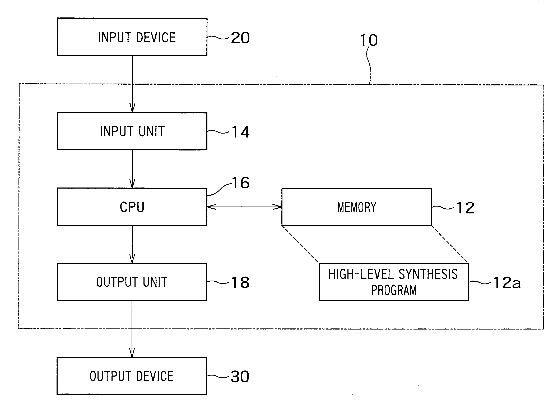
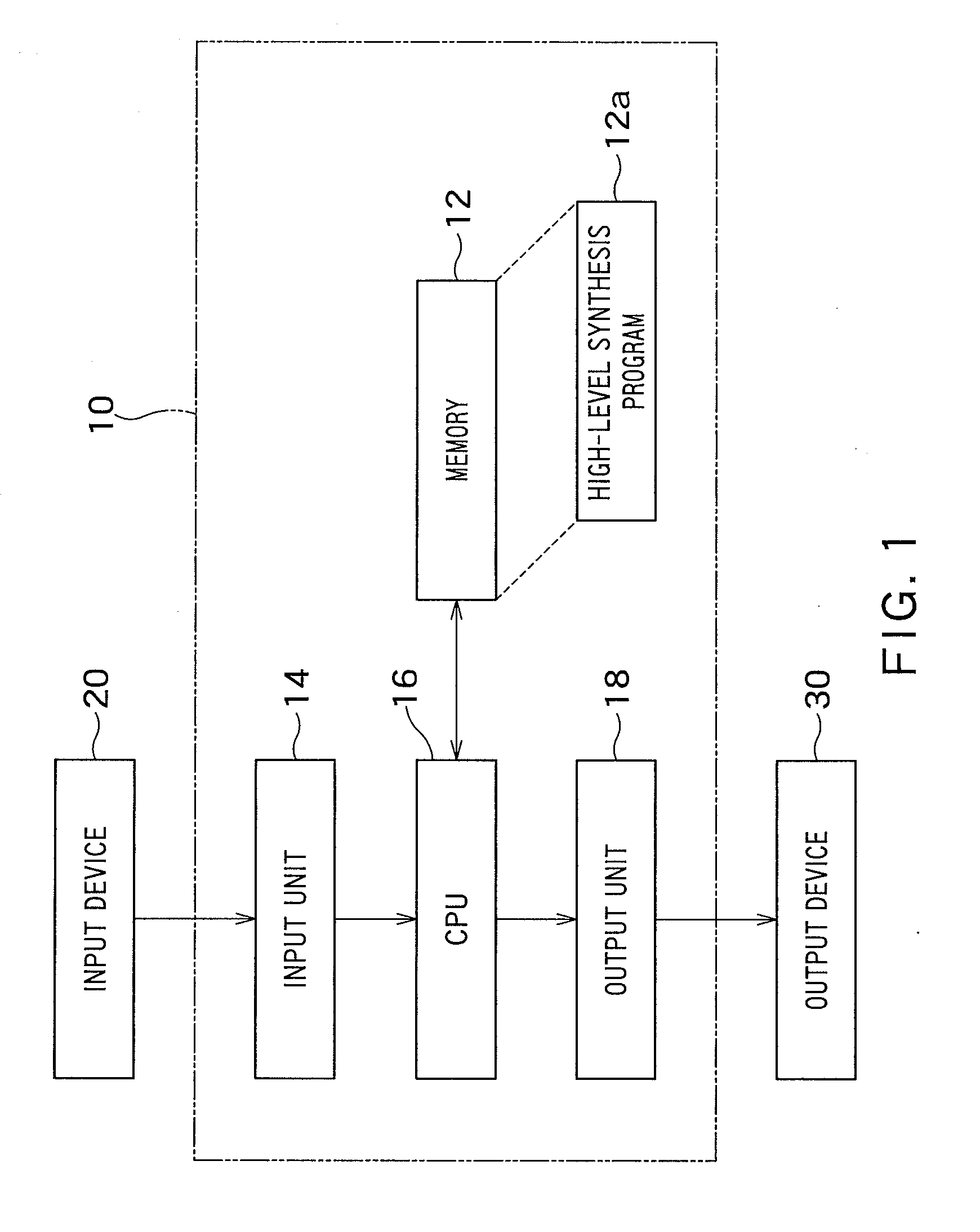
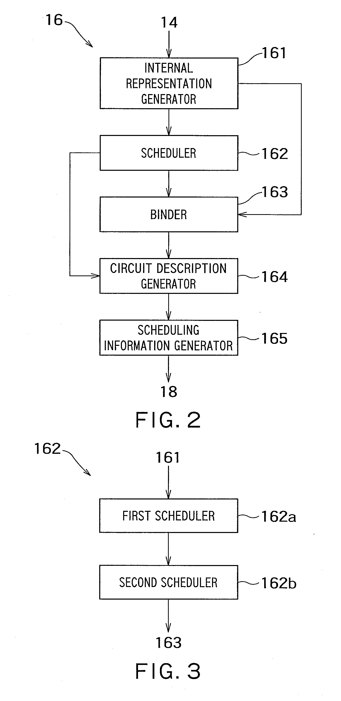
[0045]A configuration of the high-level synthetic apparatus according to the first embodiment will now be explained. FIG. 1 is a block diagram showing a configuration of a high-level synthesis apparatus 10 according to a first embodiment of the present invention. FIG. 2 is a block diagram showing functions which are realized by a CPU 16 in FIG. 1. FIG. 3 is a block diagram showing functions of a scheduler 162 in FIG. 2.

[0046]As shown in FIG. 1, a high-level synthesis apparatus 10 includes a memory 12, an input unit 14, a processor (hereinafter referred to as “central processing unit (CPU)”) 16, and an output unit 18. The CPU 16 is connected to the memory 12, the input unit 14, and the output unit 18. Input data to the high-level synthesis apparatus 10 includes a source code of a behavioral level description ...

second embodiment

[0077]A second embodiment of the present invention will now be explained. The second embodiment is an example of a high-level synthesis apparatus that performs the scheduling on each of CDFGs which are divided (hereinafter referred to as “divided CDFG”). A description of the same contents as the above-described embodiment will be omitted.

[0078]A configuration of a high-level synthesis apparatus according to the second embodiment will now be explained. FIG. 7 is a block diagram showing functions of a scheduler 162 according to the second embodiment of the present invention.

[0079]As shown in FIG. 7, the scheduler 162 includes the first scheduler 162a, the second scheduler 162b, and a divider 162c. The first scheduler 162a is the same as that according to the first embodiment.

[0080]The divider 162c in FIG. 7 is configured to divide the internal representation after the first scheduling is performed by the first scheduler 162a into a plurality of divided internal representations.

[0081]T...

third embodiment

[0090]A third embodiment of the present invention will now be explained. The third embodiment is an example of a high-level synthesis apparatus that cancels the share of the functional units when a period of time necessary in the power saving operation is not secured for the high-level synthesis results. A description of the same contents as the above-described embodiments will be omitted.

[0091]A configuration of a high-level synthesis apparatus according to the third embodiment will now be explained with reference to FIG. 2. The internal representation generator 161, the scheduler 162, the circuit description generator 164, and the scheduling information generator 165 in FIG. 2 are the same as those in the second embodiment, respectively.

[0092]The binder 163 in FIG. 2 is configured to perform the binding on the second results scheduled by the second scheduler 162b. In the binding, a new functional unit is allocated to share-cancelled operations when the non-operating cycles necessa...


PUM


Abstract

A high-level synthesis apparatus includes an input unit inputting a behavioral description indicating a behavior of a semiconductor integrated circuit comprising a plurality of functional units, an internal representation generator generating an internal representation based on the behavioral description, the internal representation showing a data flow in the behavioral description and an order in which operations are to be performed in the behavioral description, a scheduler performing scheduling for the operations in the internal representation generated in such a manner that non-operating cycles of the functional units continue, a binder performing binding for determining a configuration of the semiconductor integrated circuit operates scheduled operations on the internal representation generated, a circuit description generator generating a circuit description based on a scheduled result and a bound result, and an output unit outputting the internal representation and the circuit description.

Description

CROSS-REFERENCE TO RELATED APPLICATION[0001]This application is based upon and claims the benefit of priority from the prior Japanese Patent Application No. 2009-207458, filed on Sep. 8, 2009; the entire contents of which are incorporated herein by reference.BACKGROUND OF THE INVENTION[0002]1. Field of the Invention[0003]The present invention relates to a high-level synthesis apparatus, a high-level synthesis method, and a computer readable medium comprising a high-level synthesis program and, specifically, those for use in design of a semiconductor integrated circuit.[0004]2. Related Art[0005]Recently, as a method for reducing a period for designing a large scale integration (LSI), a method is known for using a conventional high-level synthesis apparatus that generates a circuit description based on a behavioral description fed by user. The conventional high-level synthesis apparatus generates the circuit description in such a manner that one functional unit performs the same kind ...

Claims


Application Information

Patent Timeline
IPC IPC(8): G06F17/50
CPCG06F17/505G06F30/327
Inventor KOJIMA, YOHEI
Owner KK TOSHIBA
Learn More