Digital microscope

a microscope and digital technology, applied in the field of digital microscopes, can solve the problem that microscopes are only useful for viewing images

Inactive Publication Date: 2011-03-10
THE GILLETTE CO
View PDF10 Cites 6 Cited by
  • Summary
  • Abstract
  • Description
  • Claims
  • Application Information

AI Technical Summary

Problems solved by technology

As a result, these microscopes are only useful for viewing images in two-dimensions, as if from directly above the surface of an object.

Method used


Image

  • Digital microscope
  • Digital microscope
  • Digital microscope

Examples


Embodiment Construction

[0013]The invention is applicable to digital microscopes, particularly to hand-held digital microscopes.

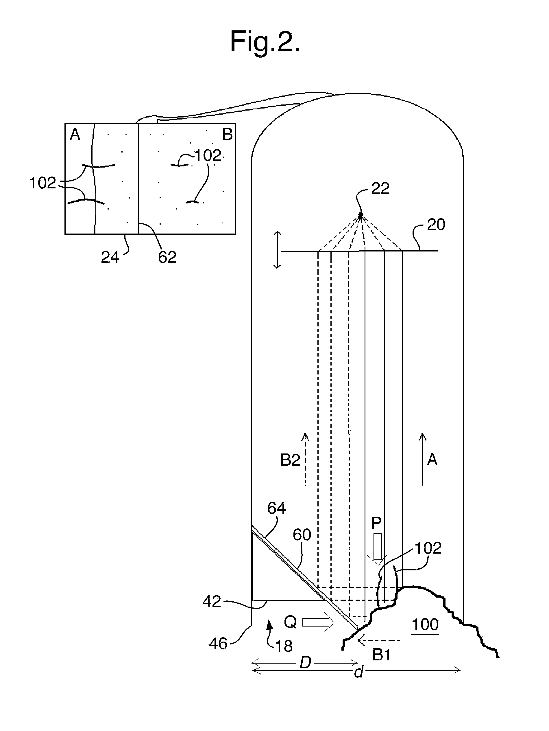
[0014]FIG. 1 shows a perspective view of a digital microscope 10 formed of a housing 12 having a proximal end 14 and a distal end 16. The distal end 16 forms an opening 18 to the housing 12. In use, the opening 18 is pressed against or placed near objects intended for viewing. A lens 20 is located within the housing, perpendicular to a length, l, of the housing 12. The lens 20 is movable between the proximal 14 and distal 16 ends of the housing 12 to allow a user to focus on an object to be viewed. A sensor 22 is provided between the lens 20 and the proximal end 14 of the housing. In use, light is reflected from the surface of an object to the lens 20 and subsequently focused on the sensor 22. The sensor 22 is preferably a charge-coupled device (CCD) that captures the reflected light and converts it to digital data that is recorded for the microscope, in the manner of a camera. A ...


PUM


Abstract

A digital microscope for viewing the surface of an object comprises a housing having a proximal end and a distal end. The distal end forms an opening to the housing. A sensor that receives light reflected from the surface of an object is located towards the proximal end of the housing. The sensor converts the light to a digital image. A lens that focuses light reflected from the object onto the sensor is located within the housing between the sensor and the object to be viewed. A reflective member is located within the opening. In use, light is reflected from the object to the sensor and a portion of the reflected light is directed via the reflective member such that the surface of the object can be viewed simultaneously from two different directions.

Description

CROSS REFERENCE TO RELATED APPLICATION(S)[0001]This application claims priority to and the benefit of EP Application No. 09169160.0, filed Sep. 1, 2009, the content of which is hereby incorporated by reference in its entirety.FIELD OF THE INVENTION[0002]The present invention relates to a digital microscope having a reflective member located at a distal end.BACKGROUND OF THE INVENTION[0003]Digital microscopes provide a convenient means for viewing magnified images. Digital microscopes use optics and sensors to record or output a magnified image to a monitor. Digital microscopes can be attached to a standard camera having a built-in screen, or they can be connected directly to a computer using a Universal Serial Bus (USB) connection. When a microscope is attached to a computer, an image can be shown on an associated screen without additional hardware.[0004]Digital microscopes with USB connections that are currently on the market are typically hand-held and can be held like a pen for t...

Claims


Application Information

Patent Timeline
Patent Type & Authority Applications(United States)
IPC IPC(8): H04N7/18G02B23/16
CPCG02B21/361G02B21/0008
Inventor OGLESBY, OLIVER DAVIDPASKINS, KEITH EDWARD
Owner THE GILLETTE CO
Why Eureka
Try Eureka