
Hybrid Conditioner for a Power System

a power system and hybrid technology, applied in the direction of harmonic reduction arrangement, power conversion system, ac network to reduce harmonics/ripples, etc., can solve the problems of power quality problems, power systems designed to function at the fundamental frequency of the system may experience unsatisfactory operation and/or failure, and the amount of reactive power provided is typically not enough to provide effective compensation

Active Publication Date: 2011-03-10
GE ENERGY POWER CONVERSION TECH
View PDF19 Cites 47 Cited by
  • Summary
  • Abstract
  • Description
  • Claims
  • Application Information

AI Technical Summary

Benefits of technology

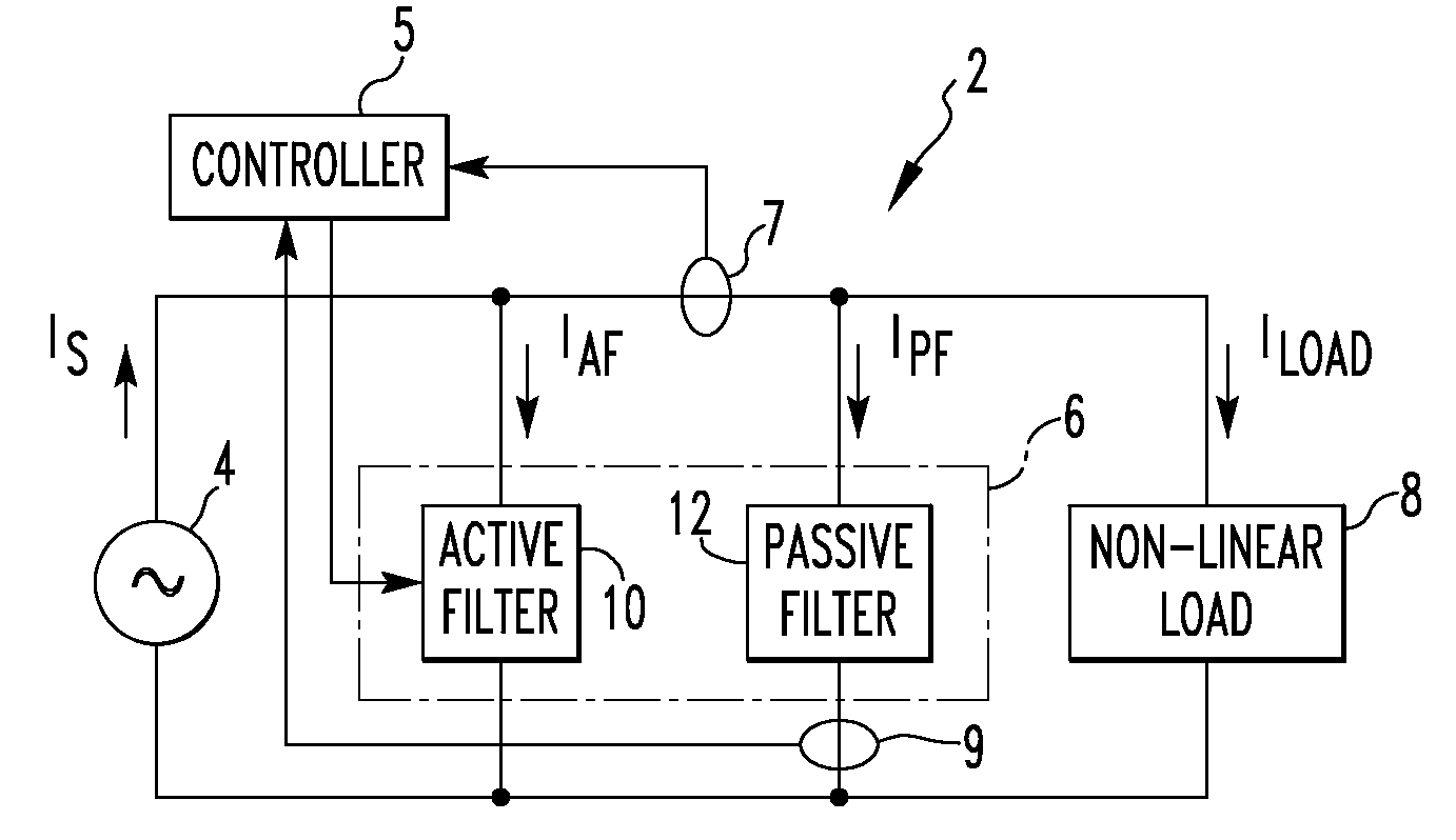
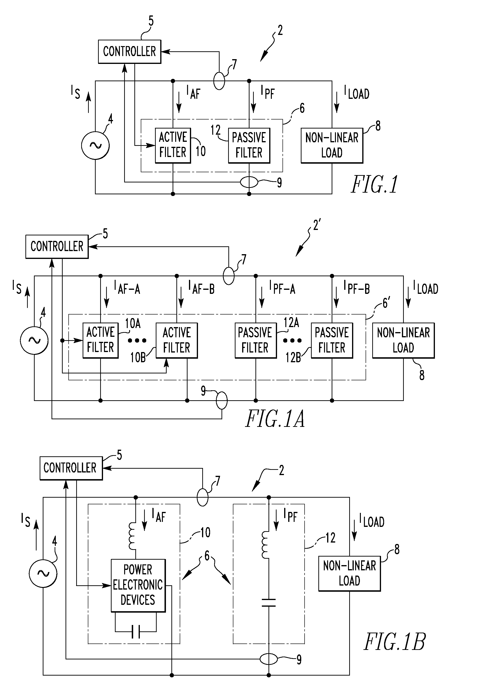
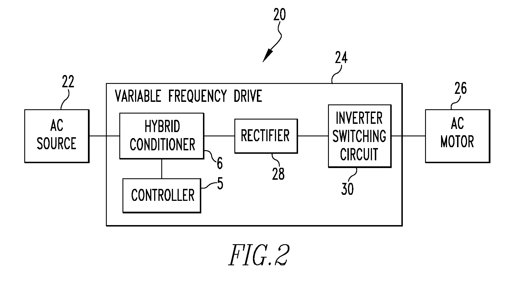
[0007]In one embodiment, the present invention provides a hybrid conditioner for filtering harmonics in a power system that includes a non-linear load, such as a variable frequency drive, and an AC source which generates AC power at a fundamental frequency f. The hybrid conditioner includes an active filter structured and controlled to filter one or more high-order harmonic currents of the fundamental frequency f, and a passive filter structured to filter one or more low-order harmonic currents of the fundamental frequency f. The active filter and the passive filter are electrical...

Problems solved by technology

Harmonic frequencies in a power system are a frequent cause of power quality problems.
In addition, power systems designed to function at the fundamental frequency of the system may experience unsatisfactory operation and / or failure when subjected to voltages and currents that contain substantial harmonic elements.
At the same time, the passive filters provide reactive power naturally, although the amount of the reactive power they provide is typically not enough to provide effective compensation for the reactive power described above.
While a passive filter performs well in filtering a particular order of harmonics, it tends to couple with the power line impedance to form an oscillation circuit and thus introduces oscillating current.

Method used


Image

  • Hybrid Conditioner for a Power System
  • Hybrid Conditioner for a Power System
  • Hybrid Conditioner for a Power System

Examples


Embodiment Construction

[0021]Directional phrases used herein, such as, for example and without limitation, top, bottom, left, right, upper, lower, front, back, and derivatives thereof, relate to the orientation of the elements shown in the drawings and are not limiting upon the claims unless expressly recited therein.

[0022]As employed, herein, the statement that two or more parts or components are “coupled” together shall mean that the parts are joined or operate together either directly or through one or more intermediate parts or components.

[0023]As employed herein, the term “number” shall mean one or an integer greater than one (i.e., a plurality).

[0024]As employed herein, the term “passive filter” shall mean an electrical circuit or device consisting of only passive components (e.g., resistors, inductors and capacitors), and not any power electronic devices (as defined herein), that is used to provide a current path for harmonics.

[0025]As employed herein, the term “active filter” shall mean an electri...


PUM


Abstract

A hybrid conditioner for filtering harmonics in a power system that includes a non-linear load. The hybrid conditioner includes an active filter structured and controlled to filter one or more high-order harmonic currents of the fundamental frequency, and a passive filter structured to filter one or more low-order harmonic currents of the fundamental frequency. The active filter and the passive filter are electrically connected in parallel with one another. The hybrid conditioner may also be for providing reactive power compensation for the power system, wherein the active filter is further controlled to provide a compensatory reactive power for compensating for the reactive power that is consumed by the load. The hybrid conditioner may also provide oscillation dampening for the power system, wherein the active filter is further controlled to damp oscillating currents that exist between the passive filter and the AC source.

Description

FIELD OF THE INVENTION[0001]The present invention relates to a hybrid conditioner for a power system, and in particular to a hybrid conditioner for a power system that includes both a passive filter and an active filter connected in parallel with the load of the power system for filtering harmonics and / or providing reactive power compensation and / or oscillation dampening for the power system.BACKGROUND OF THE INVENTION[0002]When a sinusoidal voltage is applied to a linear load, the current drawn by the load is a sinusoidal current at the same frequency as the voltage (although usually not in phase with the voltage). In contrast, when a sinusoidal voltage is applied to a non-linear load, such as a rectifier, the current drawn by the load is non-sinusoidal. Instead, the current waveform is complex and consists of a series of multiple sinusoidal signals that start at the fundamental frequency of the power system and occur at integer multiples of the fundamental frequency known as harmo...

Claims


Application Information

Patent Timeline
IPC IPC(8): H02J1/02
CPCY02E40/40H02J3/01
Inventor ZHANG, JINHUI
Owner GE ENERGY POWER CONVERSION TECH
Learn More