Method for estimating and correcting a drift between clocks of a receiving transceiver and a corresponding emitting transceiver, and receiver for implementing said method

a clock offset and receiver technology, applied in the direction of pulse technique, amplitude demodulation, line-faulst/interference reduction, etc., can solve the problem that the clock offset tracking and synchronization of high-precision oscillators cannot be used to generate the clock on these devices, and the synchronization and clock offset tracking are particularly difficult,

Inactive Publication Date: 2011-03-03
ECOLE POLYTECHNIQUE FEDERALE DE LAUSANNE (EPFL)
View PDF11 Cites 20 Cited by
  • Summary
  • Abstract
  • Description
  • Claims
  • Application Information

AI Technical Summary

Problems solved by technology

Furthermore, because the design objective of IEEE 802.15.4 devices is low-cost, low-power and low complexity, high precision oscillators cannot be used to generate the clock on these devices.
In IEEE 802.15.4a, synchronization and clock offset tracking are especially challenging because the fine temporal resolution of UWB signals requires high timing accuracies.
Further, IR-UWB signals lack a continuous sinusoidal carrier....

Method used


Image

  • Method for estimating and correcting a drift between clocks of a receiving transceiver and a corresponding emitting transceiver, and receiver for implementing said method
  • Method for estimating and correcting a drift between clocks of a receiving transceiver and a corresponding emitting transceiver, and receiver for implementing said method
  • Method for estimating and correcting a drift between clocks of a receiving transceiver and a corresponding emitting transceiver, and receiver for implementing said method

Examples


Embodiment Construction

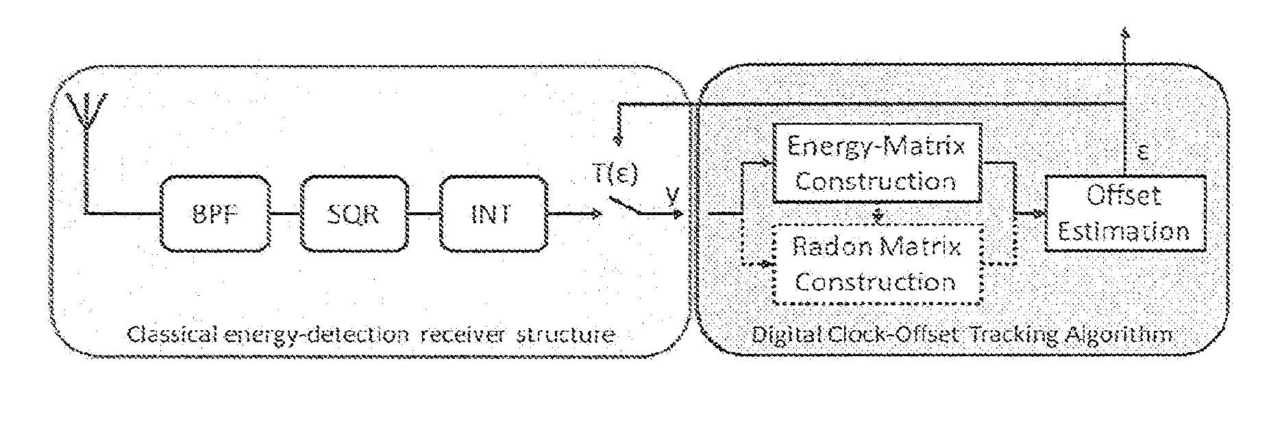
[0064]In what follows, the invention is described in the context of a non-coherent receiving transceiver or receiver based on energy detection. Further, we use the signaling model of the IEEE 802.15.4a preamble part as an example. This is only done for simplicity and to serve as an example. Most of the concepts can be extended in a straightforward way to other receiver architectures (e.g. coherent), other signaling formats (e.g. the data part of an IEEE 802.15.4a packet or any other IR-UWB or pulse-based signaling format). Where an extension is not straightforward, we will comment on how it can be done.

1) System Model and Assumptions: Assume a packet structure as it is used e.g. in IEEE 802.15.4a. According to this standard, FIG. 1 shows on the upper part, a packet structure comprising a preamble and a payload. The lower part of FIG. 1 illustrates the preamble. As an example, in FIG. 1, the preamble part of the packet is formed of a ternary preamble code sequence s=(+1, +1, 0, −1). ...


PUM


Abstract

Method for estimating and correcting a frequency offset between a local clock of a receiving transceiver and a remote clock of an emitting transceiver comprises receiving by said receiving transceiver, a signal emitted by the emitting transceiver, said signal lacking a continuous sinusoidal carrier and having at least one symbol, each symbol being emitted within a time frame having a first duration; sampling the signal by taking for each time frame a set of energy measurements of said signal; forming a matrix representative of said energy measurements; determining from said energy matrix, points of maximum of energy within each time frame; determining a line connecting a plurality of said points within each of said time frames; determining a slope of said line; calculating a frequency offset between the clocks of the emitting and receiving transceivers using the slope; and adjusting the receiving transceiver's clock frequency according to the frequency offset.

Description

CLAIM TO PRIORITY[0001]This application claims priority under 35 U.S.C. Section 119(a) to European patent application no. EP09169176.6, the entire contents of which are hereby incorporated herein by reference.TECHNICAL FIELD[0002]The present invention relates to a clock offset tracking and synchronization method suitable for low-complexity receivers communicating via impulse-radio ultra-wideband (IR-UWB) radio transmission or other pulse based signals.[0003]More specifically, the invention concerns a method for estimating and correcting a frequency offset between the clocks of transceivers that communicate via electromagnetic signals that lack a continuous sinusoidal carrier, thereby implying that methods for correcting frequency offsets that require the presence of a continuous sinusoidal signal cannot be used. In particular, this method applies when two electronic devices communicate without having a common reference clock, but each device has its own free running clock. This meth...

Claims


Application Information

Patent Timeline
IPC IPC(8): H04L27/00
CPCH04L7/0054
Inventor FLURY, MANUELMERZ, RUBENLE BOUDEC, JEAN-YVES
Owner ECOLE POLYTECHNIQUE FEDERALE DE LAUSANNE (EPFL)
Why Eureka
Try Eureka