Liquid crystal display device

Inactive Publication Date: 2011-03-03
HITACHI CONSUMER ELECTRONICS CORP
View PDF6 Cites 6 Cited by
  • Summary
  • Abstract
  • Description
  • Claims
  • Application Information

AI Technical Summary

Benefits of technology

[0006]In recent years, liquid crystal display devices, while being made thinner, have been growing larger in screen size. The tandem-type backlight device described above is, compared with other types of backlight device, advantageous in making liquid crystal display device thinner and larger in screen size.
[0008]A tandem-type backlight device is configured using such light guide plates and LEDs arranged in plural blocks (light guide plate blocks). In a tandem-type backlight device including plural light guide plate blocks, however, a clearance and a mechanical deformation can be generated between light guide plate blocks because of differences between them as to thermal expansion or contraction dependent on, for example, their materials, dimensions, and shapes. Such the clearance and the deformation cause brightness unevenness (differences in brightness level) in the output light of the backlight device or on the screen of the liquid crystal display device. The brightness unevenness can be eliminated by increasing the distance between the light guide plate and the diffusion sheet, but doing so increases the thickness of the backlight device.
[0009]The present invention has been made in view of the above problem and it is an object of the invention to provide a liquid crystal display device in which the generation of the clearance and the mechanical deformation between light guide plate blocks resulting from their thermal expansions or contractions caused by temperature changes is reduced.
[0019]According to the present invention, a surface light source unit and a liquid crystal display device using the same can be provided in which clearances or mechanical deformations generated between divided blocks when such blocks are thermally expanded or contracted as a result of a temperature change are reduced. Therefore, unevenness of the light outputted from the surface light source unit and the brightness unevenness of the liquid crystal display device can be reduced.
[0020]The present invention can also provide a liquid crystal display device in which no clearance is formed between divided blocks so as not to allow mechanical deformations to be generated between such blocks when such blocks are thermally expanded or contracted. It is therefore possible to reduce the distance between the surface light source and a diffusion sheet and thereby reduce the thickness of the liquid crystal display device.

Problems solved by technology

Such the clearance and the deformation cause brightness unevenness (differences in brightness level) in the output light of the backlight device or on the screen of the liquid crystal display device.

Method used


Image

  • Liquid crystal display device
  • Liquid crystal display device
  • Liquid crystal display device

Examples


Embodiment Construction

[0030]Embodiments of the present invention will be described below with reference to the accompanying drawings. In the accompanying drawings, identical components having identical functions are denoted by identical reference numerals, and their descriptions are omitted where appropriate to avoid duplication. Also, any enlarged view of a component drawn for use in relevant description may not represent the real dimensional proportions of the component and, moreover, different portions of the component may be drawn differently enlarged even along a same dimensional direction.

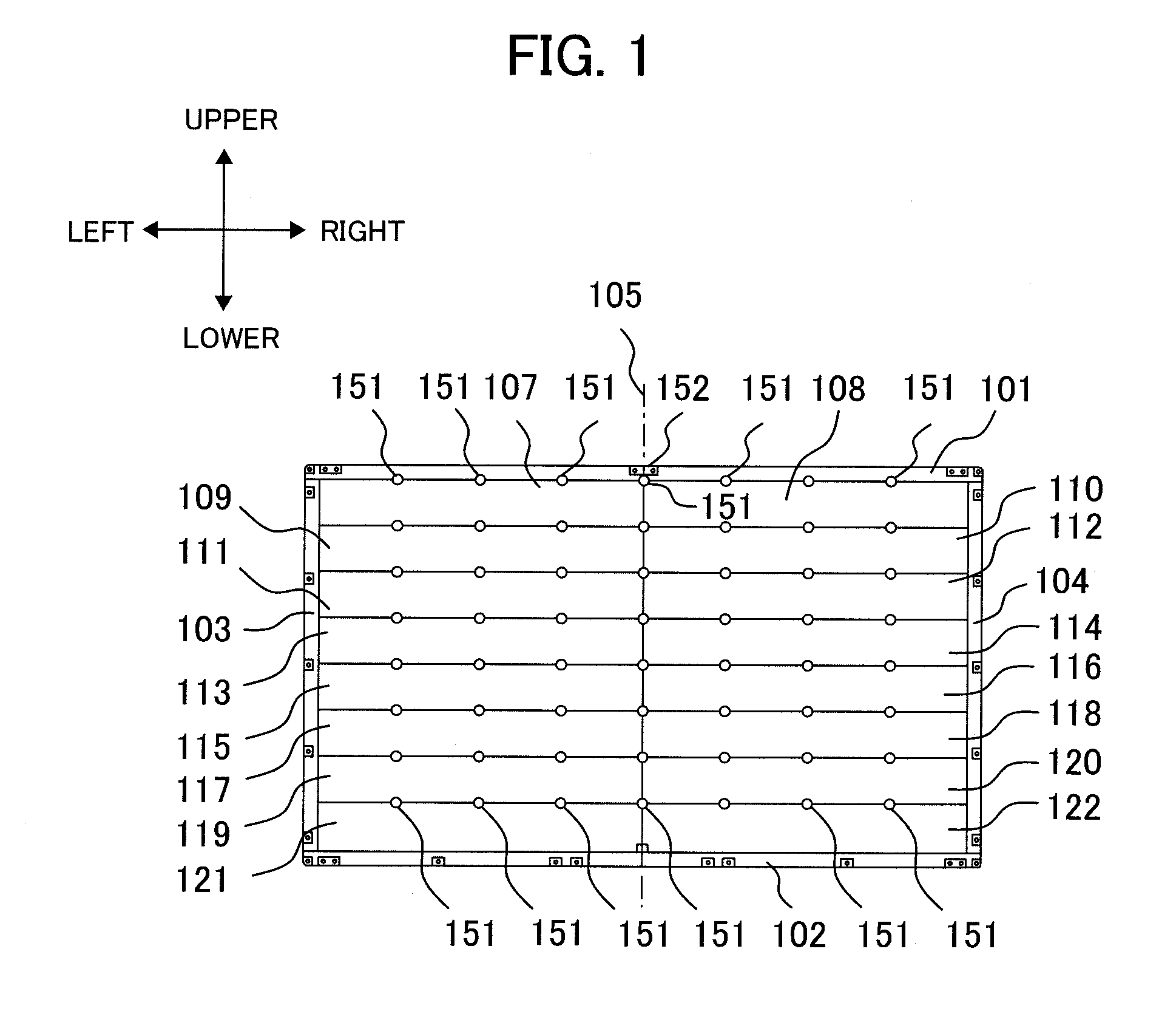
[0031]The directions such as front-rear (front-back), upper-lower (vertical), and left-right (horizontal) directions denoted by arrows in the accompanying drawings are as seen by a viewer facing the screen of a liquid crystal display device placed on a flat surface (desktop installation). This also applies to the descriptions associated with the accompanying drawings. In this specification, items, for example, pow...


PUM


Abstract

A liquid crystal display device is provided in which, even when divided light guide plate blocks are thermally expanded or contracted as a result of a temperature change, the generation of clearances and mechanical deformations between such divided light guide plate blocks is prevented, making it possible to reduce the brightness unevenness of the liquid crystal display device. To realize the above feature, light guide plate blocks are arranged such that one or two of them are arranged in each horizontal row with only an upper side of each light guide plate block fixed to a chassis and, furthermore, such that the upper side fixed to the chassis of each light guide plate block is based on a center in the horizontal direction of the liquid crystal display panel so as to reduce the effects of thermal expansion and contraction of each light guide plate block.

Description

BACKGROUND OF THE INVENTION[0001](1) Field of the Invention[0002]The present invention relates to a liquid crystal display device, particularly, a liquid crystal display device using a backlight device which converts, using light guide plates, the illumination light outputted from light emitting diodes into surface light and outputs the surface light to a liquid crystal panel.[0003](2) Description of the Related Art[0004]There have been edge-light (side-light) type backlight devices in which light is supplied from a side and direct type backlight devices in which light is supplied from behind (from a rear side). In edge-light type backlight devices, light emitted from a primary light source, for example, a cold cathode fluorescent lamp (CCFL) or a light emitting diode (LED) is converted into surface light using a light guide plate formed of a highly scattering optical transmission (HSOT) polymer or a transparent material. Such edge-light type backlight device is widely used in liqui...

Claims


Application Information

Patent Timeline
IPC IPC(8): G02F1/13357
CPCG02B6/008G02F1/133615G02F1/133608G02B6/0088
Inventor SATO, KATSUNARIYAMASHITA, YOSHIHARU
Owner HITACHI CONSUMER ELECTRONICS CORP
Why Eureka
Try Eureka