
Passive marine equipment recovery device

a recovery device and equipment technology, applied in the field of equipment, can solve the problems of equipment damage, slow recovery process, equipment damage,

Inactive Publication Date: 2011-03-03
PGS ONSHORE INC
View PDF7 Cites 12 Cited by
  • Summary
  • Abstract
  • Description
  • Claims
  • Application Information

AI Technical Summary

Benefits of technology

[0008]A system according to one aspect of the invention for retrieving a device from the bottom of a body of water includes a clamp configured to be slidably affixed to the device above the water bottom. The clamp has a selectively engageable lock to fix a position of the clamp on the device. A line ratchet is coupled to the clamp. A line is disposed through the line ratchet. A first flotation device is c

Problems solved by technology

When so disposed, recovery can be difficult due to the device being covered with ocean bottom material.
As a result, recovery of the equipment can be a slow difficult process.
A difficulty with the foregoing recovery method is that the equipment is often damaged from the stresses applied and personnel and recovery equipment spend a substantial amount of time pulling on the equipment to dislodge it from the water bottom sediment rather than attending to the other duties.

Method used


Image

  • Passive marine equipment recovery device
  • Passive marine equipment recovery device
  • Passive marine equipment recovery device

Examples


Embodiment Construction

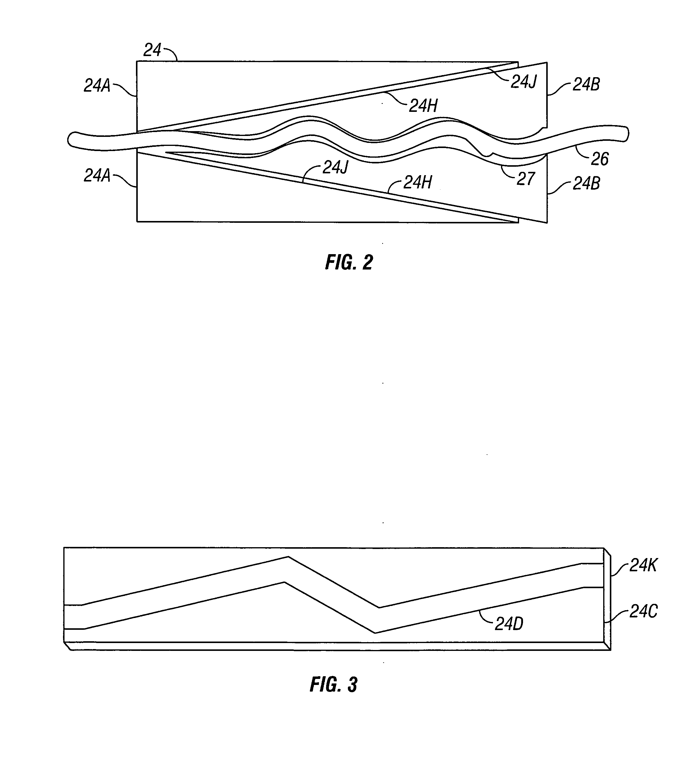
[0017]An example system for retrieving devices deployed on the bottom of a body of water is shown schematically in FIG. 1. A device, such as a cable or conduit 26 may be deployed on the bottom of a body of water 10 such as a lake or the ocean. The cable or conduit 26 (referred to for convenience hereinafter as the “cable”) may be, for example, a seismic sensor cable. After the cable 26 has been deployed for a selected length of time, parts of the cable 26 may become partially or totally buried by water bottom sediment 28. The weight of such sediment may make retrieval of the cable 26 by pulling upwardly on its axial end difficult and may risk breakage of or damage to the cable 26 by reason of excessive axial tension required to lift the cable 26 from the sediment 28.

[0018]The present system may include a first floatation device such as a buoy 12 coupled to a storage element 14. The storage element 14 may be a bag or a reel (a bag is shown in FIG. 1) and is configured to store portio...


PUM


Abstract

A system for retrieving a device from the bottom of a body of water includes a clamp configured to be slidably affixed to the device above the water bottom. The clamp has a selectively engageable lock to fix a position of the clamp on the device. A line ratchet is coupled to the clamp. A line is disposed through the line ratchet. A first flotation device is coupled to one end of the line. A second flotation device is coupled to the other end of the line. The system includes means for applying tension to the line disposed proximate the second flotation device. The line ratchet is arranged to enable movement of the line therethrough toward the means for applying tension, and is also arranged to substantially prevent motion therethrough in the opposite direction.

Description

CROSS-REFERENCE TO RELATED APPLICATIONS[0001]Not applicable.STATEMENT REGARDING FEDERALLY SPONSORED RESEARCH OR DEVELOPMENT[0002]Not applicable.BACKGROUND OF THE INVENTION[0003]1. Field of the Invention[0004]The invention relates generally to the field of equipment such as cables and conduits deployed on the bottom of a body of water. More specifically, the invention relates to devices for recovering such cables or conduits after they have been deployed on the water bottom for a selected length of time.[0005]2. Background Art[0006]The invention is related to a device that is intended to be attached to equipment or material, e.g., a seismic sensor cable or a conduit, disposed on the bottom of a body of water such as a lake or the ocean. When so disposed, recovery can be difficult due to the device being covered with ocean bottom material. As a result, recovery of the equipment can be a slow difficult process. Recovery of the equipment requires that the equipment is pulled laterally a...

Claims


Application Information

Patent Timeline
IPC IPC(8): B66D1/00
CPCB63C7/20F16G11/10F16G11/04B63C7/26F16G11/105
Inventor SCOTT, GARY LEE
Owner PGS ONSHORE INC
Learn More