
Plasma processing apparatus

a processing apparatus and plasma technology, applied in the direction of coatings, chemical vapor deposition coatings, electric discharge tubes, etc., can solve the problems of deterioration of maintenanceability, affecting the etching uniformity of substrate surfaces, and inability to smoothly introduce processing gas into the processing container, so as to increase the removability of adhered products

Active Publication Date: 2011-03-03
TOKYO ELECTRON LTD
View PDF15 Cites 371 Cited by
  • Summary
  • Abstract
  • Description
  • Claims
  • Application Information

AI Technical Summary

Benefits of technology

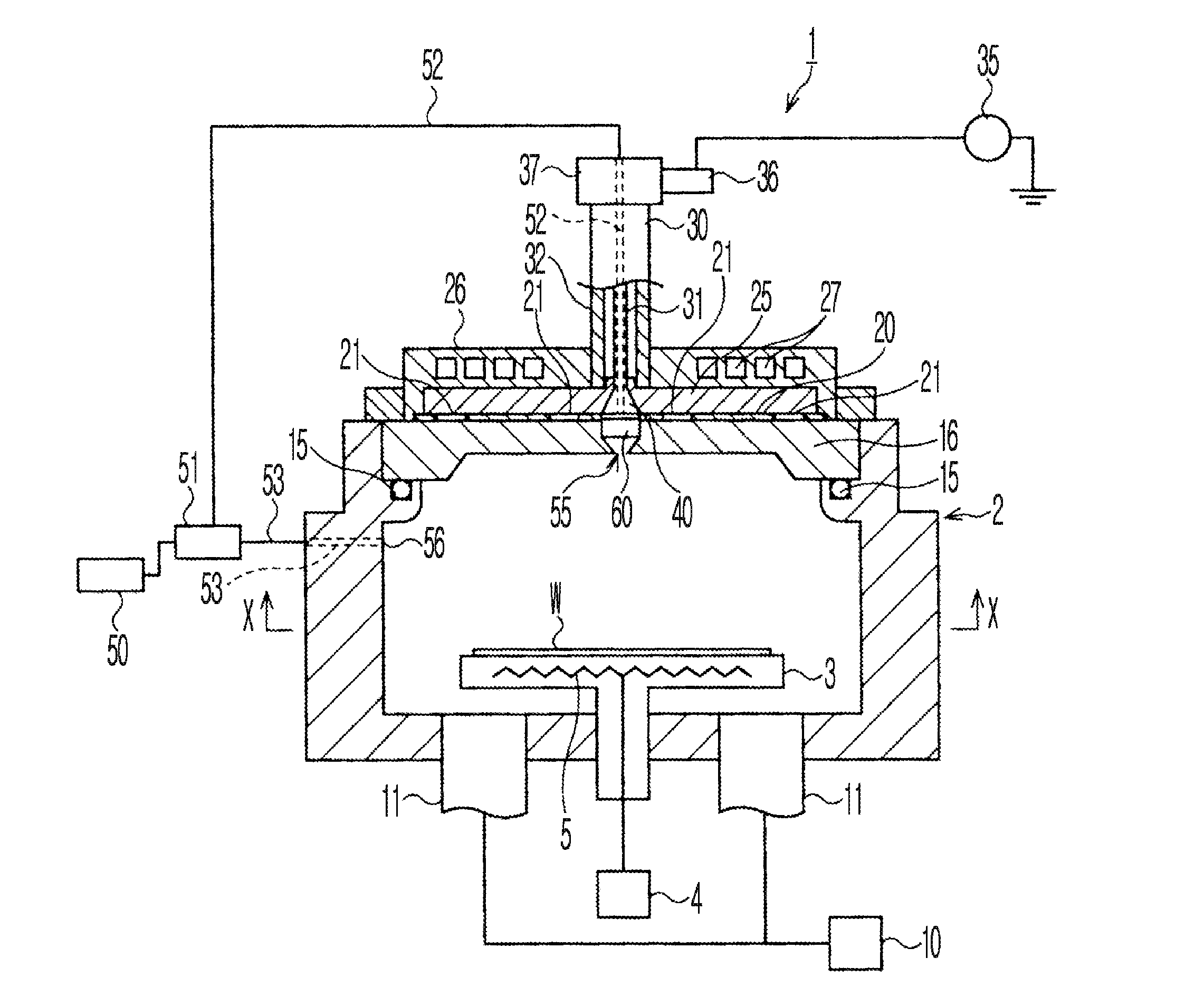
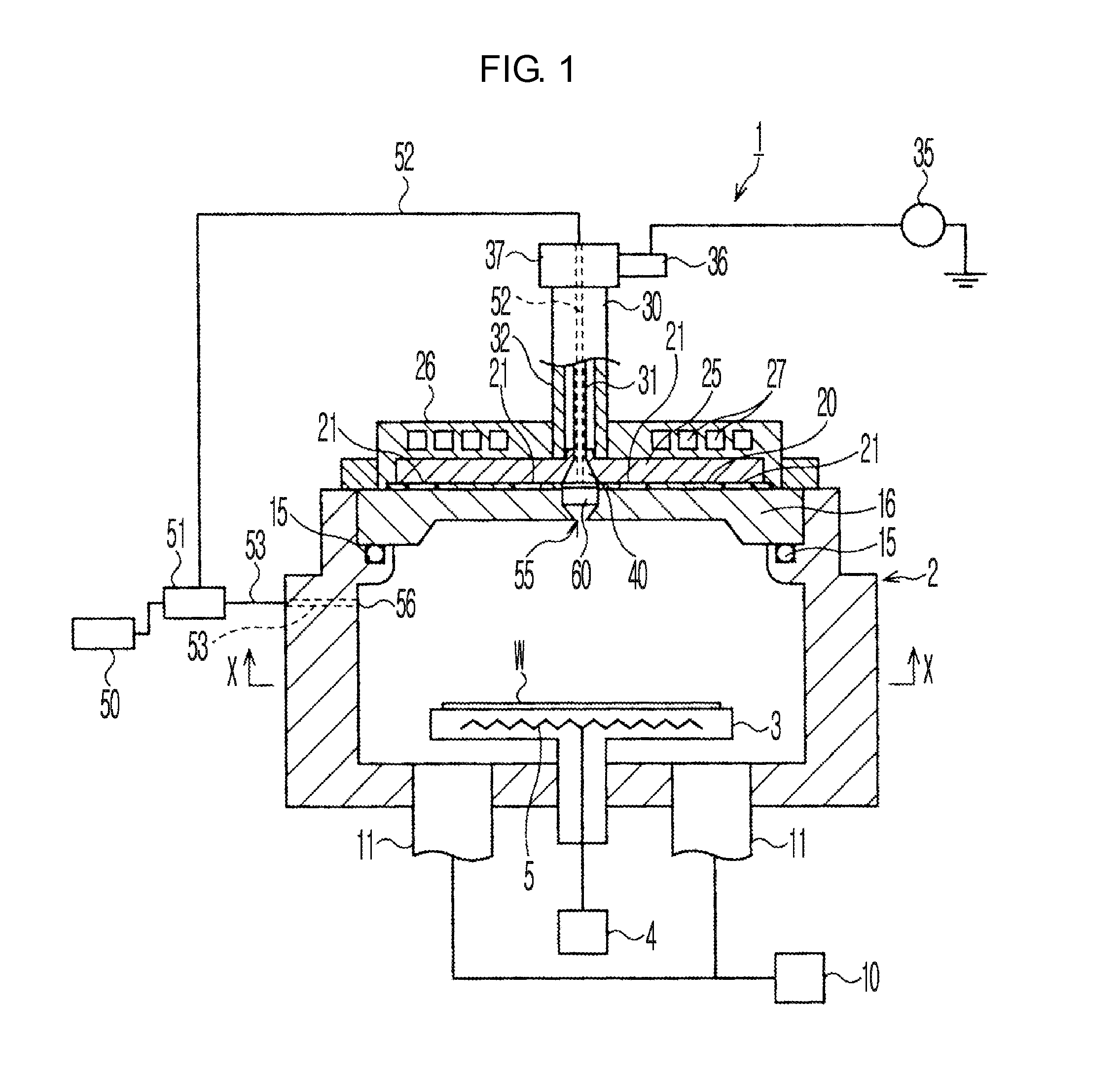
[0010]According to an aspect of the present invention, there is provided a plasma processing apparatus which processes a substrate by plasmatizing a process gas introduced into a processing container, wherein an introducing unit which introduces the process gas is formed on a ceiling surface of the processing container; a gas retention portion in which the process gas supplied from the outside of the processing container via a supply passage stays tentatively before being distributed, and a plurality of gas ejection holes which allow communication between the gas retention portion and the inside of the processing container are formed in the introducing unit; a gas ejection hole is not formed in a location of the gas retention portion that faces an opening of the supply passage; and a cross section of each of the gas ejection holes has a flat shape.

Problems solved by technology

Also, the process gas may be unable to be smoothly introduced to the processing container as a gas ejection hole formed in the introducing unit is blocked by the adhered product.
When the gas ejection hole is blocked by the adhered product, a balance between the amounts of process gases introduced from an introducing unit on a side surface and an introducing unit on a ceiling surface may change, and thus etching uniformity over a surface of a substrate may deteriorate.
Moreover, an operation of solving a blocking of the gas ejection hole is troublesome, and thus maintenanceability is deteriorated.

Method used


Image

  • Plasma processing apparatus
  • Plasma processing apparatus
  • Plasma processing apparatus

Examples


embodiments

[0060]A relationship between a cross-sectional shape of a gas ejection hole formed in an injector block and an internal pressure of a gas retention portion is examined.

embodiment 1

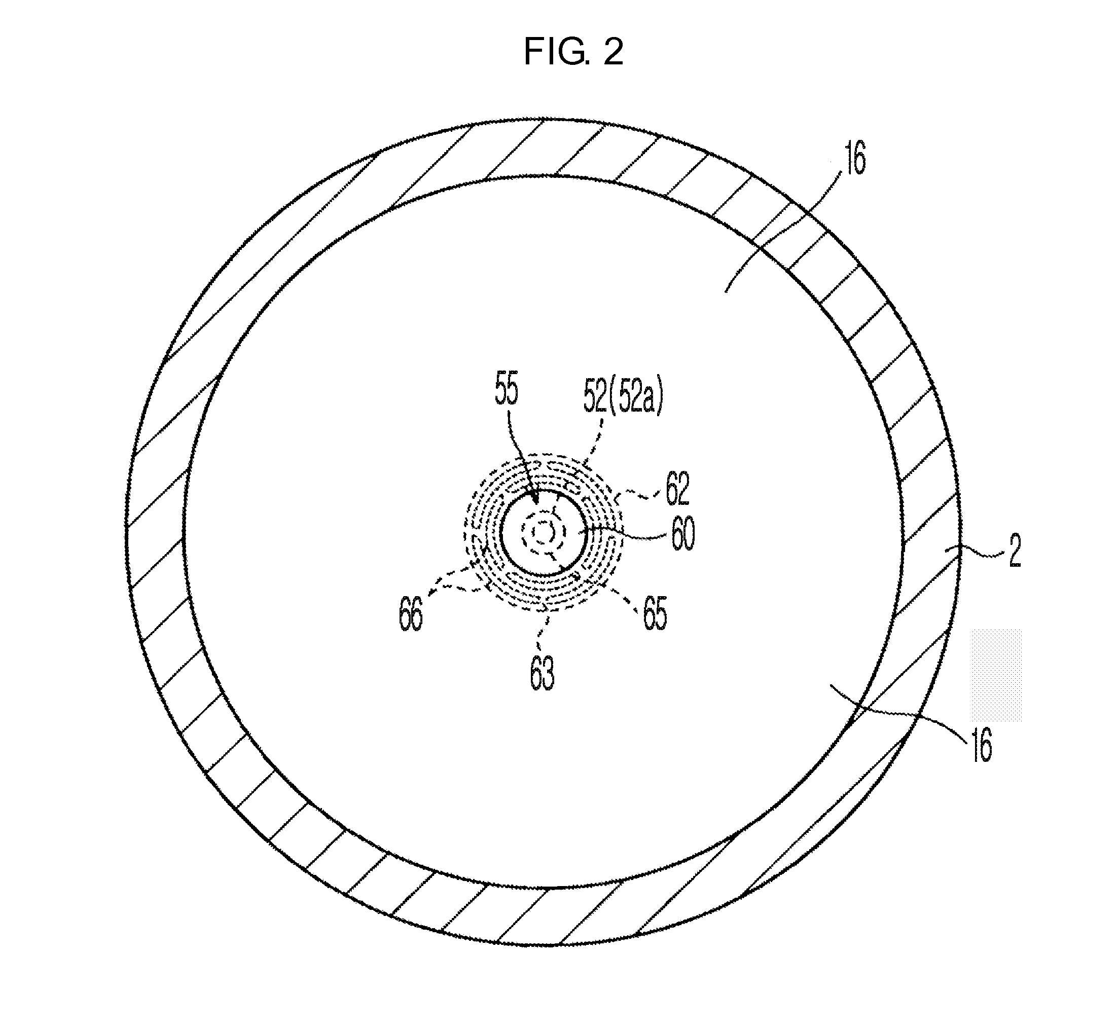
[0065]As shown in FIG. 8(e), in Embodiment 1, 24 gas ejection holes 66 each having a flat cross-sectional shape are formed in the injector block 60 having a disc shape with a thickness of 8 mm. The width t of the gas ejection hole 66 in the radial direction of the injector block 60 is 0.5 mm, and the length L thereof in the circumferential direction of the injector block 60 is from several mm to ten and several mm. No gas ejection holes 66 are formed on the center of the injector block 60, which is a location facing an opening of a supply passage of a process gas. Also, the recess portion 65 is formed in the center of the upper surface of the injector block 60.

embodiment 2

[0066]As shown in FIG. 8(f), in Embodiment 2, 12 gas ejection holes 66 each having a flat cross-sectional shape are formed in the injector block 60 having a disc shape with a thickness of 8 mm. The width t of the gas ejection hole 66 in the radial direction of the injector block 60 is 0.5 mm, and the length L thereof in the circumferential direction of the injector block 60 is from several mm to ten and several mm. No gas ejection holes 66 are formed on the center of the injector block 60, which is a location facing an opening of a supply passage of a process gas. Also, the recess portion 65 is formed in the center of the upper surface of the injector block 60.


PUM

PropertyMeasurementUnit
Lengthaaaaaaaaaa
Dielectric polarization enthalpyaaaaaaaaaa
Shapeaaaaaaaaaa

Abstract

In a plasma processing apparatus for processing a substrate by plasmatizing a process gas introduced into a processing container, an introducing unit which introduces the process gas is formed on a ceiling surface of the processing container; a gas retention portion which gathers the process gas supplied from the outside of the processing container through a supply passage, and a plurality of gas ejection holes which allow communication between the gas retention portion and the inside of the processing container are formed in the introducing unit; a gas ejection hole is not formed in a location of the gas retention portion that faces an opening of the supply passage; and a cross section of each of the gas ejection holes has a flat shape.

Description

CROSS-REFERENCE TO RELATED PATENT APPLICATIONS[0001]This application claims the benefit of Japanese Patent Application No. 2009-202634, filed on Sep. 2, 2009, in the Japan Patent Office, the disclosure of which is incorporated herein in its entirety by reference.BACKGROUND OF THE INVENTION[0002]1. Field of the Invention[0003]The present invention relates to a plasma processing apparatus used in semiconductor manufacturing.[0004]2. Description of the Related Art[0005]Plasma processing apparatuses that generate plasma by propagating microwaves from slots formed in a Radial Line Slot Plate (Radial Line Slot Antenna: RLSA) into a processing container are conventionally used in the manufacturing field of semiconductor devices (for example, refer to Patent Document 1). These RLSA-type plasma processing apparatuses are capable of forming uniform plasma having high density and a low electron temperature, and performing plasma-process of large-sized semiconductor wafers uniformly and fast. A...

Claims


Application Information

Patent Timeline
IPC IPC(8): H01L21/465
CPCH01J37/32192H01J37/32449C23C16/513H01J37/3244H01L21/67069
Inventor MIHARA, NAOKIMATSUMOTO, NAOKIYOSHIKAWA, JUNMURAKAMI, KAZUO
Owner TOKYO ELECTRON LTD
Learn More