
Line synchronization

a line synchronization and synchronization technology, applied in the field of systems, can solve the problems of poor weight precision of the portion, the inability to synchronize the portioning yield of the line during operation, and the inability to meet the requirements of the customer, so as to achieve simple and reliable line synchronization, avoid the disadvantages of the higher-level controller, and simplify the system for producing and transporting food portions.

Active Publication Date: 2011-02-24
VEMAG MASCHENBAU
View PDF10 Cites 0 Cited by
  • Summary
  • Abstract
  • Description
  • Claims
  • Application Information

AI Technical Summary

Benefits of technology

[0014]A signal which originates at the subsequent processing machine reports to the filling machine when portions are to be produced. This signal is a portion request signal for the continuously operating filling machine. The disadvantages of discontinuous operation of the filling machine, including rapid wear and high waste of food, are avoided by using the continuously operating filling machine. Fluctuations in the power grid leading to fluctuations of portions per minute can also be evened out because the machines run synchronously. More specifically, the filling machine is synchronized with the subsequent processing device.
[0021]Preferably the control unit is designed to stop the operation of the filling machine and the separating device if no clock cycle is received for a certain time. Consequently, a production backup or empty line can be prevented.

Problems solved by technology

However, if continuously operating machines in a line define the moment when portions are produced in order for the line to work optimally, that operation results in a contradiction of competing interests.
Such a system has the disadvantage that the starting and stopping operation may result in poor weight precision for the portions.
Such systems have the disadvantage that the portioning yield of the line may drop during operation, for example, from 101 to 99 portions per minute because of fluctuations in the power grid.
As a result, the portions are either too heavy or the production is interrupted by a malfunction.

Method used


Image

  • Line synchronization
  • Line synchronization
  • Line synchronization

Examples


Embodiment Construction

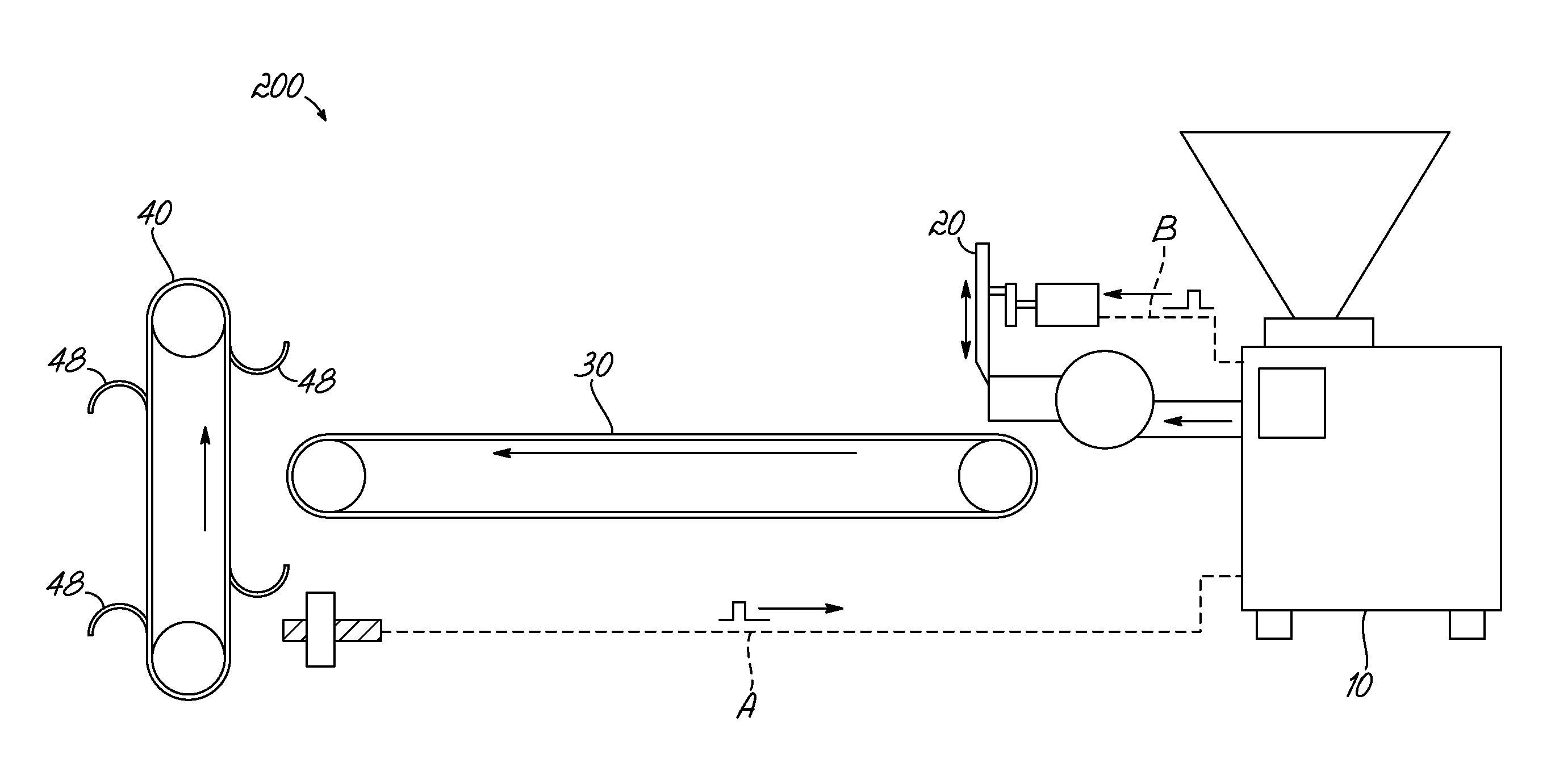
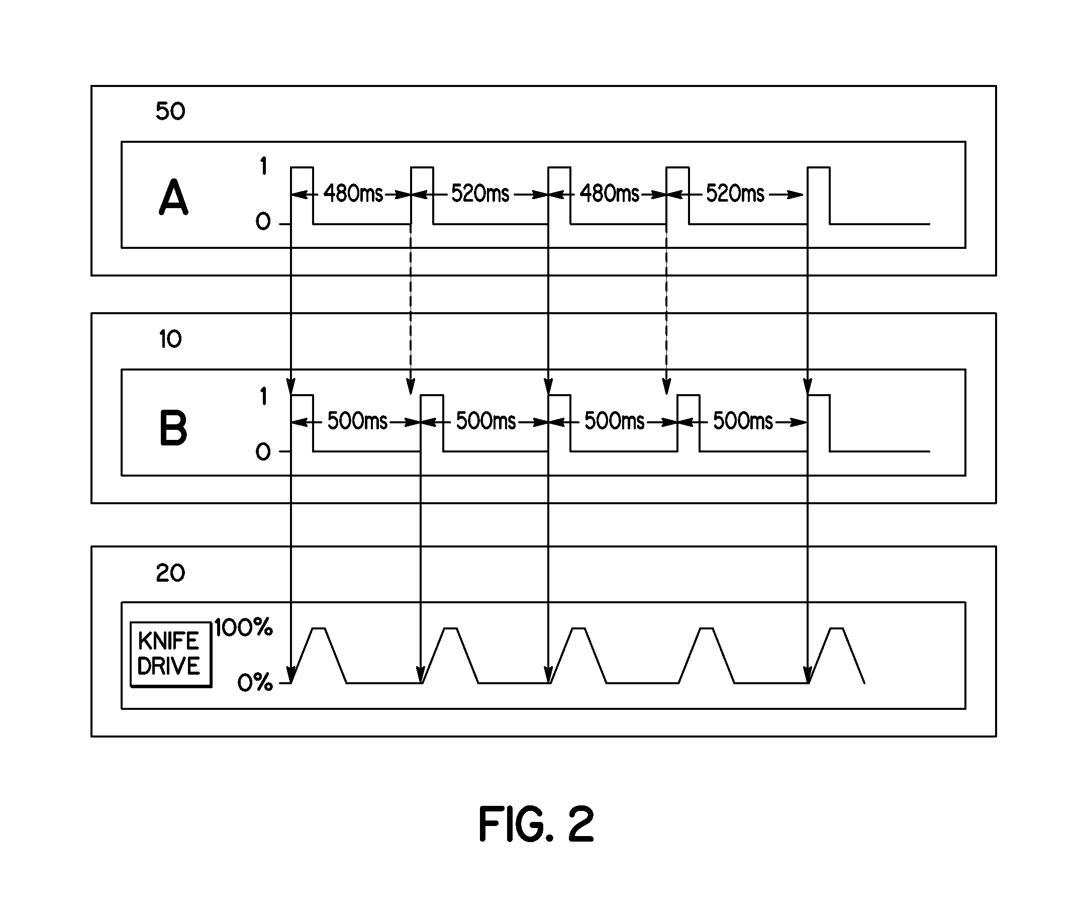
[0036]FIG. 1 illustrates schematically a system 200 according to one embodiment of the invention for producing and transporting food portions. The system 200 includes a filling machine 10 for continuously transporting a food stream. The system 200 also includes a separating device 20, which is designed to separate portions from the transported food stream. The system 200 further includes a transporting device 30 for transporting the portions to a subsequent processing device 40. The transporting device 30 is preferably a conveyor belt. The system 200 also includes a sensor unit 50 designed to generate a portion request signal A on the basis of a portion request produced by the subsequent processing device 40. The sensor unit 50 issues the portion request signal A to the filling machine 10. The subsequent processing device 40 may include a device for packaging the individual portions.

[0037]To ensure that every one of the packages 48, indicated schematically in FIG. 1 by semicircles o...


PUM

PropertyMeasurementUnit
Lengthaaaaaaaaaa
Timeaaaaaaaaaa
Shapeaaaaaaaaaa

Abstract

A system for producing and transporting portions of food includes a filling machine for continuously transporting a stream of food, a separating device for dividing portions from the transported food stream, and a transport device for delivering the portions to a subsequent processing device. To prevent fluctuations in portion size and weight, the system further includes a sensor unit for generating a portion request signal in response to a portion request from the subsequent processing device. The sensor unit outputs the portion request signal to the filling machine, which is designed to control the continuous transportation of the food stream using the portion request signal. The system is operable to synchronize the entire line, including the filling machine, the separating device, the transport device, and the subsequent processing device.

Description

TECHNICAL FIELD[0001]The present invention relates to a system and a method for producing and transporting food portions, and more specifically, to a system including a filling machine for continuous transportation of a stream of food.BACKGROUND[0002]Food portions are frequently produced as follows: A food supply is stored in a filling machine, and is dispensed from the filling machine to a cut-off device. The cut-off device divides the stream of food delivered by the filling machine into individual portions and delivers these portions to a conveyor belt or other transport apparatus. The conveyor belt transports the food portion to a subsequent processing device, which packages or reshapes the food portion or carries out other work steps thereon.[0003]Various designs, interactions, and methods of operation of the individual components are known. The filling machine, for example, can operate in a start-and-stop mode, i.e., the filling machine starts to deliver the stream of food in r...

Claims


Application Information

Patent Timeline
IPC IPC(8): B65B57/00A47J44/00A23P1/00
CPCA21C9/08A21C3/10
Inventor KIEL, TOBIASMEIER, DIETERCARSTENS, CHRISTIANALDAG, UWE
Owner VEMAG MASCHENBAU
Learn More