
Apparatus and method for performing fused multiply add floating point operation

a technology of adding circuitry and apparatus, applied in the field of data processing, can solve the problems of reducing precision at the expense of extra range, and achieve the effect of reducing the amount of processing performed by the adding circuitry

Active Publication Date: 2011-02-17
ARM LTD
View PDF1 Cites 42 Cited by
  • Summary
  • Abstract
  • Description
  • Claims
  • Application Information

AI Technical Summary

Benefits of technology

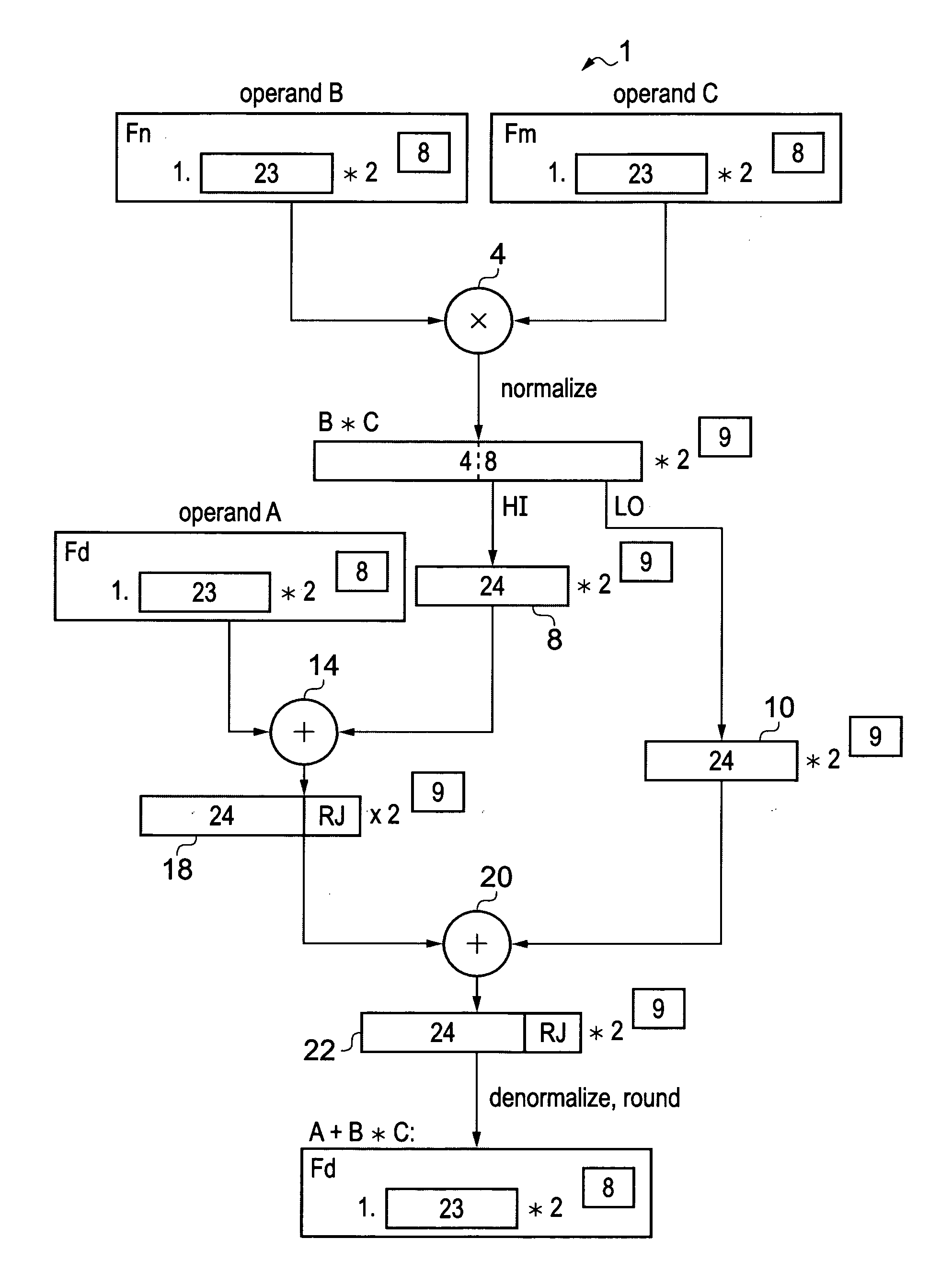
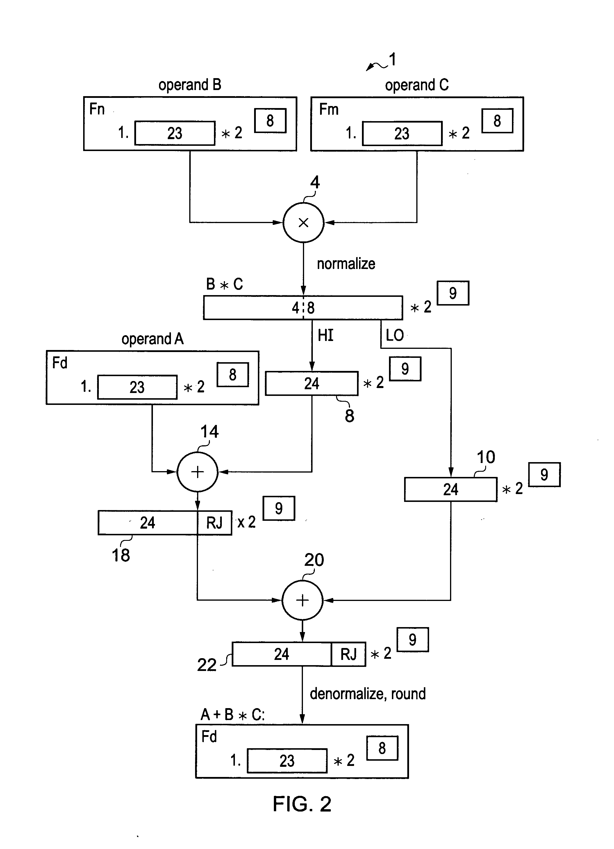
[0014]The present technique recognizes that a fused multiply add operation can be performed using adders and shifters of a similar width to those used to perform simple floating point addition. This is done by splitting the product of operands B and C into a high order portion and a low order portion. In a first addition, operand A is added to one of the high order portion and low order portion to generate an intermediate sum value. Then, in a second addition, the intermediate value is added to a remaining one of the high order portion and the low order portion in order to generate the result A+B*C. By breaking the addition up into stages, adding circuitry of a similar width to that used to perform simple addition can be used to perform the multiply add operation. For example, if single precision is being used, then adding circuitry comprising adders and shifters having a width of approximately 24 bits can be used to add a 48-bit product to a 24-bit addend, while retaining the higher precision associated with the fused multiply add operation. While the present technique achieves this reduction in circuit area at the expense of increased processing time, in many smaller processors the latency required for executing the fused multiply add operation is not critical and reducing the circuit area overhead is more important than reducing the processing time.
[0063]Floating point subtraction is usually best performed in the order ‘larger absolute value minus smaller absolute value’, with the sign bit adjusted accordingly. However, a precise calculation of which of the values is larger can take a significant amount of processing. To reduce the amount of processing, the adding circuitry estimates which of the product B*C and the operand A has the larger absolute value, rather than calculating this precisely. The two-step adder of the present technique means that even if the estimation is incorrect and the first or second intermediate value is generated with an incorrectly negative or positive value, this can be accounted for during the second step (since the incorrectly negative or positive value will also have an incorrect sign bit, and so the second step will produce the correct result regardless). Thus, the present technique avoids the need for any negating or processing of the first or second intermediate value between being generated in the first adding step and being used for the second adding step. Thus, the selected intermediate value can be passed unchanged between the first and second adding steps and the amount of processing performed by the adding circuitry can be reduced.

Problems solved by technology

However, the extra range is achieved at the expense of reduced precision since some of the bits are used to store the exponent.
The wide adders and shifters that are typically used for the fused multiply add represent a significant area overhead, particularly for smaller processors.

Method used


Image

  • Apparatus and method for performing fused multiply add floating point operation
  • Apparatus and method for performing fused multiply add floating point operation
  • Apparatus and method for performing fused multiply add floating point operation

Examples


Embodiment Construction

[0085]FIG. 2 schematically illustrates an apparatus 1 for performing a fused multiply add operation. In the apparatus, operands A, B and C are provided to the apparatus 1. In the example where single precision floating point representation is used, each operand has a 23-bit fractional part F of the mantissa (usually in the form 1.F, although the mantissa could be in the denormal form 0.F) and an 8-bit exponent E. Note that, while in the Figures the exponent is often indicated in the form 2[x] (where X is the number of bits used to store the exponent), the actual number of places by which the radix point of the floating point value is shifted relative to the mantissa is the X-bit exponent value biased by 127 as shown in FIG. 1. Also, while not illustrated in FIGS. 2-9, each floating point value would also have a sign bit S indicating whether the value is positive or negative.

[0086]Operands B and C are multiplied together by a multiplier 4. The multiplier 4 generates a normalized prod...


PUM


Abstract

A data processing apparatus is arranged to perform a fused multiply add operation. The apparatus 100 has multiplying circuitry 110 configured to multiply operands B and C to generate a product B*C having a high order portion 160 and a low order portion 170. The apparatus has adding circuitry 130 configured to: (i) add an operand A to one of the high order portion 160 and the low order portion 170 to generate an intermediate sum value; and (ii) add the intermediate sum value to a remaining one of the high order portion 160 and the low order portion 170 to generate a result A+B*C.

Description

BACKGROUND OF THE INVENTION[0001]1. Field of the Invention[0002]The present invention relates to the field of data processing. In particular, the invention relates to an apparatus for performing a fused multiply add floating point operation.[0003]2. Description of the Prior Art[0004]Processors for performing arithmetic operations on binary floating point numbers are known. In floating point representation, numbers are represented using a mantissa 1.F, an exponent E and a sign bit S. The sign bit S represents whether the floating point number is positive or negative, the mantissa 1.F represents the significant digits of the floating point number, and the exponent E represents the position of the radix point (also known as a binary point) relative to the mantissa. By varying the value of the exponent, the radix point can “float” left and right within the mantissa. This means that for a predetermined number of bits, a floating point representation can represent a wider range of numbers...

Claims


Application Information

Patent Timeline
Patent Type & Authority Applications(United States)
IPC IPC(8): G06F7/487
CPCG06F7/5443G06F7/483
Inventor PENTON, ANTONY JOHNCRASKE, SIMON JOHNCAULFIELD, IAN MICHAEL
Owner ARM LTD
Learn More