
Technique for detection of optical data signals

a technology for optical data and detection techniques, applied in optics, instruments, electromagnetic transmission, etc., can solve the problems that the optical communication line (an optical fiber, a free space line) containing optical amplifiers will inevitably accumulate ase nois

Active Publication Date: 2011-02-17
ECE TELECOM LTD
View PDF10 Cites 4 Cited by
  • Summary
  • Abstract
  • Description
  • Claims
  • Application Information

AI Technical Summary

Benefits of technology

It is the object of the present invention to provide a technique for detecting data carried by an optical signal transmitted via an optical communication line, which would be able to essentially reduce ASE noise accumulated during transmission of the optical signal without performing regeneration of the signal—i.e., a technique suitable even in cases when regeneration of optical signals in the line is problematic or impossible.
The proposed technique saves considerable investments for improving OSNR in the communication line (especially considerable when high bit rate data is transmitted), because the proposed technique is “passive” (uses passive elements) and bit rate independent.

Problems solved by technology

The ASE noise is one of the main impairments created in any optical communication line, together with chromatic dispersion and non-linearity.
Any optical communication line (an optical fiber, a free space line) comprising optical amplifiers will inevitably accumulate the ASE noise.

Method used


Image

  • Technique for detection of optical data signals
  • Technique for detection of optical data signals
  • Technique for detection of optical data signals

Examples


Embodiment Construction

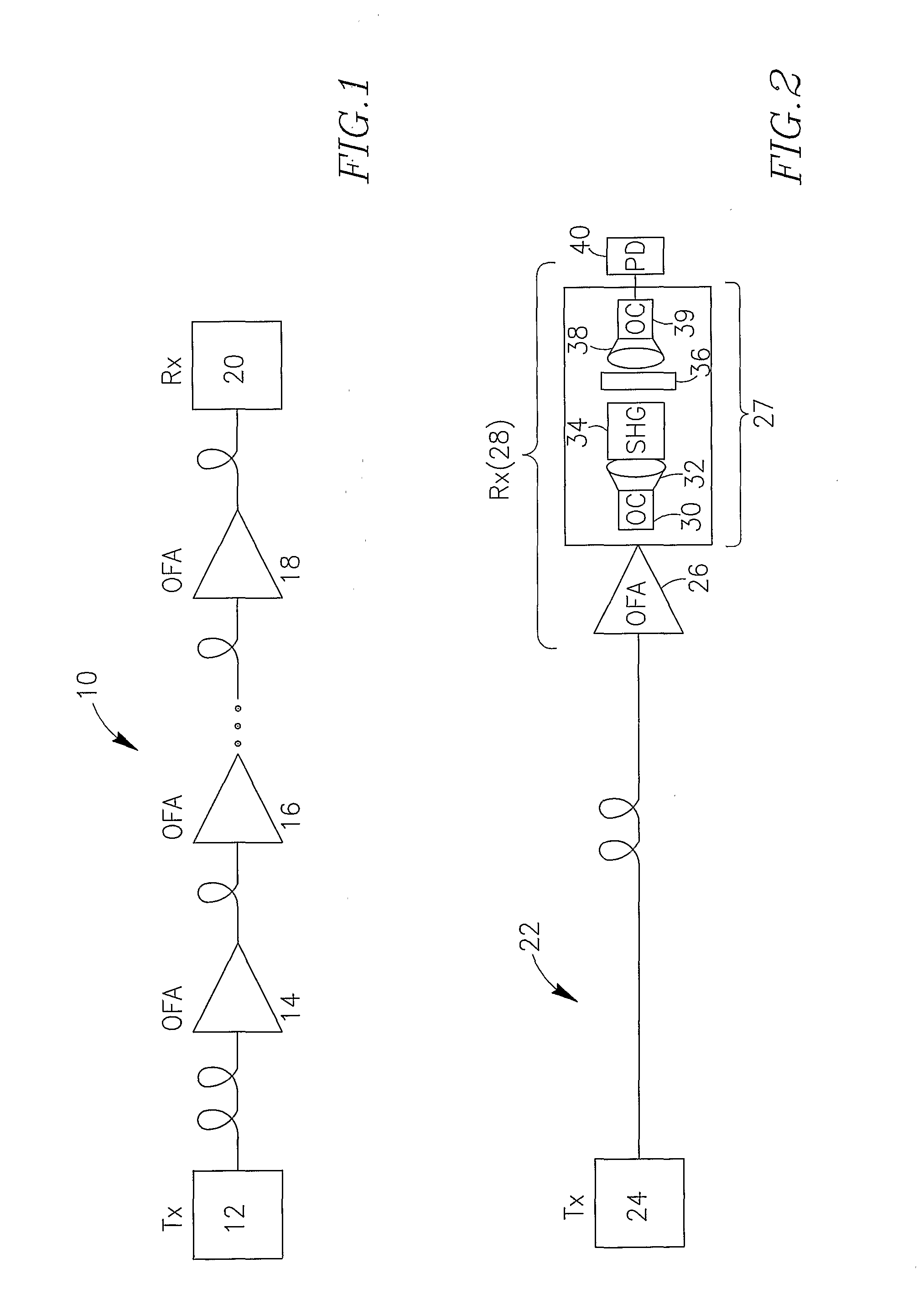
FIG. 1 (prior art) schematically shows an optical communication line 10 equipped with conventional means 14, 16, 18 for amplifying the optical data signal carried via one exemplary optical channel between a transmitter 12 and a receiver 20. The conventional means should be understood as Optical Fiber Amplifiers OFA which, while amplifying the optical signal, amplify also the accumulated noise signal and thus lead to degradation of OSNR (Optical Signal to Noise Ratio) being the main characteristic of optical signals' transmission. In this particular figure one exemplary optical channel is illustrated.

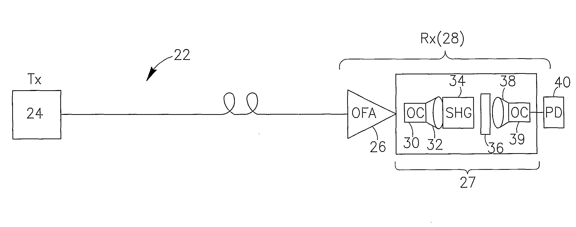
FIG. 2 shows an optical line 22 arranged according to the proposed invention. The line 22, for the purpose of example only, comprises an optical transmitter 24 for transmitting data via one optical channel, and does not require at all (or require much less) OFAs and / or optical signal regenerators (not shown) than the conventional line 10, since the line is provided with a novel data dete...


PUM


Abstract

Technology for detecting an optical data signal carried in a combined optical signal that comprises a carrier optical signal modulated by the optical data signal and also comprises ASE noise. The proposed optical data detector / receiver is provided with an SHG device adapted to generate a second harmonic optical signal of the carrier optical signal modulated by the data signal. In the signal, generated by the SHG, the ASE noise will be essentially reduced.

Description

FIELD OF THE INVENTIONThe present invention relates to equipment for optical communication networks.BACKGROUND OF THE INVENTIONA problem of noise suppression (i.e., improving Optical Signal to Noise Ratio OSNR) in long communication lines is a very complex problem, which always required great efforts and high investments at the transmitting end, at nodes of the communication line and at the receiving end. Today, there are no means that enable a network operator or designer to improve OSNR using passive components (i.e., those not comprising electro-optical schemes). For modem optical communication lines, which operate at very high bitrates, the problem becomes critical; the only way to improve OSNR in such systems is to regenerate the optical signal. A conventional signal regeneration assembly comprises expensive active blocks such as an optical receiver (Rx), an Opto-Elecro-Optic regeneration block and an optical transmitter (Tx). The regeneration cost today is approximately $10 k ...

Claims


Application Information

Patent Timeline
Patent Type & Authority Applications(United States)
IPC IPC(8): H04B10/06H04B10/67
CPCH04B10/671
Inventor MAHLAB, URIGUTIN, MICHAEL
Owner ECE TELECOM LTD
Learn More