
Transmitting Node B Load Status Information in a Self Organising Network

a self-organising network and load status technology, applied in the direction of digital transmission, network topologies, electrical appliances, etc., can solve the problems of forced network reconfiguration over a large number of cells, interference and noise between cells and channels is likely to be severe, and the user equipment cannot reach the inside of the building

Active Publication Date: 2011-02-17
NOKIA SOLUTIONS & NETWORKS OY
View PDF36 Cites 46 Cited by
  • Summary
  • Abstract
  • Description
  • Claims
  • Application Information

AI Technical Summary

Benefits of technology

[0043]The method may further comprise receiving the at least one spectrum load characteristic from th

Problems solved by technology

For example a conventional node B located outside the building may have problems reaching the user equipment inside the building due to the physical external walls.
Firstly, in such envisioned deployments of LNB network elements there is the problem of providing network configuration capabilities so that the intercell (i.e. between neighbouring cells) and co-channel interference in individual cells can be overcome or at least partially addressed.
This interference and noise between cells and channels is likely to be severe in plug-and-play local area node B deployment as the local area node B elements may be placed physically close to each other.
Actions such as the initial set-up, reconfiguration, reset or removal of a plug-and-play local area node B deployment must not be allowed to cause a significant impact on the existing operating network environment, in other words, in a communication system it is likely that introducing or removing a local area node B elements may cause a chain reaction of forced network reconfigurations over a large number of cells and not just the immediately neighbouring node B elements in the network around the newly introduced local area network B.
Furthermore, the plug-and-play local area node B elements currently have the problem that they cannot perform spectral load balancing.
These methods however rely on the X2 interface which although being present in conventional NBs is not typically available for local area node Bs in the deployment of plug-and-play LNB elements.

Method used


Image

  • Transmitting Node B Load Status Information in a Self Organising Network
  • Transmitting Node B Load Status Information in a Self Organising Network
  • Transmitting Node B Load Status Information in a Self Organising Network

Examples


Embodiment Construction

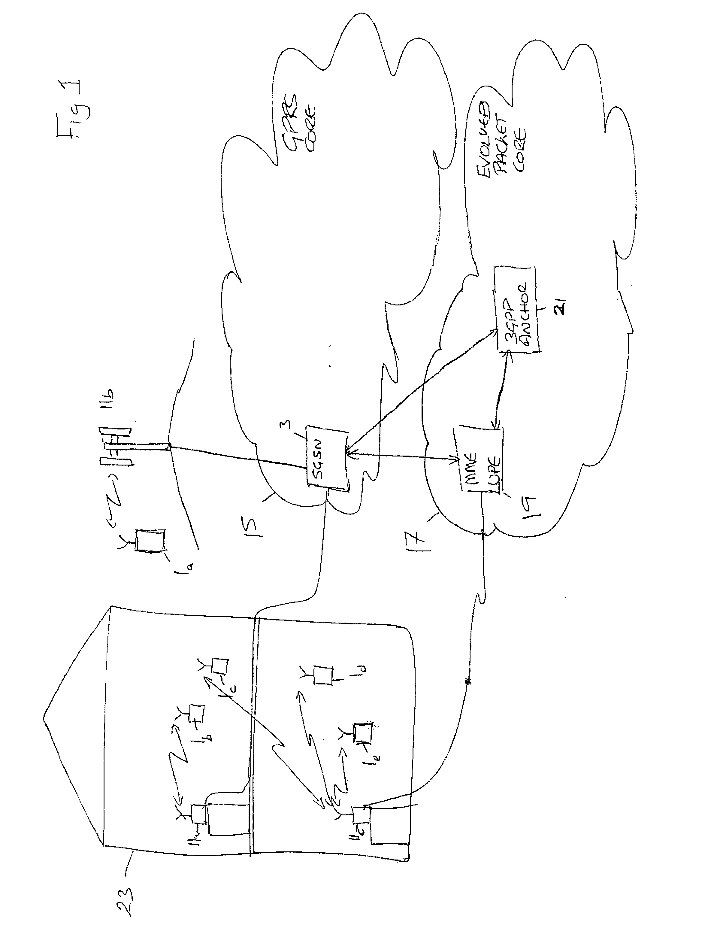
[0055]With respect to FIG. 1, a wireless communication system within which embodiments of the invention may be implemented is shown. FIG. 1 shows a conventional node B (NB) 11b which is arranged to communicate with a user device 1. The NB is furthermore configured to be connected to a serving GPRS support node (SGSN) 3. The serving GPRS support node (SGSN) is a network element responsible for the delivery of packet data to and from the mobile stations within a geographical service area via a series of node Bs or enhanced node Bs. The SGSN 3 tasks include packet routing and transfer, mobility management, logical link management and authentication and charging functions. The SGSN 3 is a component of the general packet radio services (GPRS) core 15.

[0056]The communication system shown in FIG. 1 furthermore shows a first local area node B 11a, and a further local area node B 11c. As indicated previously the access entities referred to as local area node Bs (LNB) are also known as home n...


PUM


Abstract

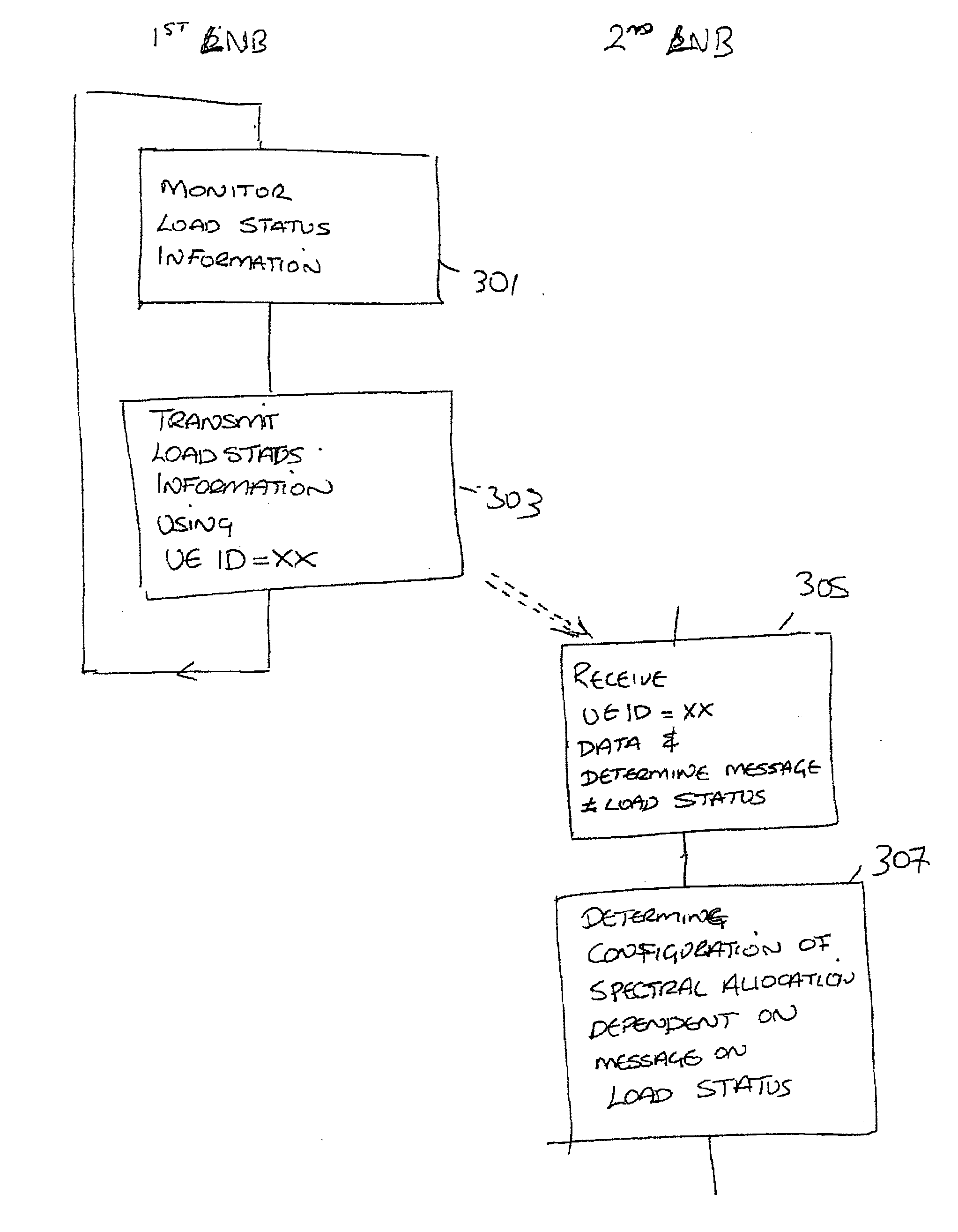
The application relates to wireless transmission of load status information for load balancing among Home Node Bs (HNB) or Local Area Node Bs (LNB) for which an X2 interface is not available. In particular, an LNB may pretend to be a user equipment with a specific predefined user equipment ID value. A neighbouring LNB which receives a data packet with this user equipment ID value knows that the data packet contains load information monitored, by a neighbouring LNB.

Description

FIELD OF THE INVENTION[0001]The present invention relates to an apparatus and in particular but not exclusively for enabling efficient spectral load balancing for a communication system. The present invention also relates to an associated system, computer program and entities.DESCRIPTION OF RELATED ART[0002]A communication device can be understood as a device provided with appropriate communication and control capabilities for enabling use thereof for communication with others parties. The communication may comprise, for example, communication of voice, electronic mail (email), text messages, data, multimedia and so on. A communication device typically enables a user of the device to receive and transmit communication via a communication system and can thus be used for accessing various service applications.[0003]A communication system is a facility which facilitates the communication between two or more entities such as the communication devices, network entities and other nodes. A...

Claims


Application Information

Patent Timeline
IPC IPC(8): H04L27/00
CPCH04W16/10H04W24/02H04W92/20H04W88/08H04W84/045
Inventor FREDERIKSEN, FRANKKLAUS INGEMANN, PEDERSENVINH, VAN PHAN
Owner NOKIA SOLUTIONS & NETWORKS OY
Learn More