Undersea seismic monitoring network

Inactive Publication Date: 2011-02-10
WIRELESS FIBER SYST
View PDF10 Cites 24 Cited by
  • Summary
  • Abstract
  • Description
  • Claims
  • Application Information

AI Technical Summary

Benefits of technology

[0015]On the other hand, the critical requirement for a communications link between the monitoring stations and an underwater vehicle is fast download, necessitating a data rate of hundreds of kilobits per second and preferably several megabits per second. To meet this requirement, the present invention provides an underwater vehicle which is employed to move between the undersea monitoring stations sequentially. The underwater vehicle engages with the undersea monitoring station, activates the station and downloads the stored data via a subsea radio communications link. Downloading of data at a very high data rate up to 100 megabits per second can take place when the underwater vehicle is located within a short range of the monitoring station. As mentioned previously, the range of transmission for high data rate communications is limited by the high attenuation of an electromagnetic signal in seawater with distance. The range limitation of high-data rate undersea communications ensures that there is no danger of interference from adjacent undersea monitoring stations, and this creates the benefit that multiple underwater vehicles can operate in parallel, downloading data from multiple undersea monitoring stations without any need to code the signals to prevent interference. Range limitation also provides the capability that the process of data transfer can be instigated automatically when the underwater vehicle comes within the range of the monitoring station.
[0025]Preferably, the plurality of monitoring stations are disposed in an array which is distributed over a given area of the seabed. In this way, seismic data can be gathered over a large area of the seabed so that a time dependent profile of the seismic data from the same area can be generated.

Problems solved by technology

As mentioned previously, the range of transmission for high data rate communications is limited by the high attenuation of an electromagnetic signal in seawater with distance.

Method used


Image

  • Undersea seismic monitoring network
  • Undersea seismic monitoring network
  • Undersea seismic monitoring network

Examples


Embodiment Construction

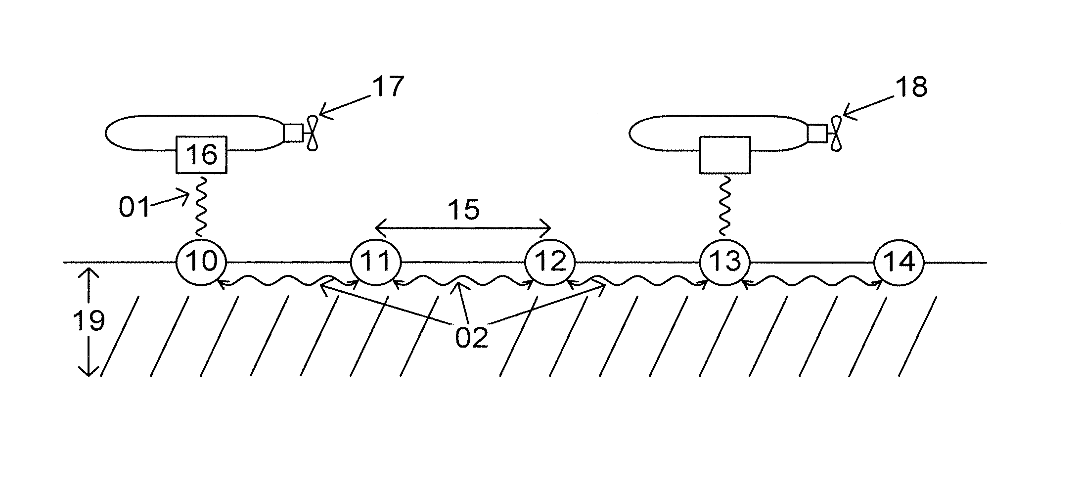
[0033]FIG. 1 shows a drawing of an undersea seismic monitoring network according to an embodiment of present invention. The undersea seismic monitoring network of FIG. 1 comprises an underwater vehicle 17, onto which a radio modem 16 is mounted, and an array of undersea monitoring stations 10, 11, 12, 13, and 14, spaced at regular intervals 15 on the seabed 19. Depending on the specific implementation, monitoring stations 10, 11, 12, 13, and 14, may be mounted on the surface of the seabed, or may be trenched; the choice is based principally on the conditions of the local environment, and the nature of the seabed.

[0034]FIG. 2 shows a block diagram of the integral components of an undersea monitoring station 10, 11, 1213 and 14 of the undersea seismic monitoring network of FIG. 1. Undersea seismic monitoring stations 10, 11, 13 and 14 each comprise a sensor 23 for measuring seismic data, which is connected to controller 20. Controller 20 comprises a programmable integrated circuit and...


PUM


Abstract

The present invention provides an undersea seismic monitoring network, the monitoring network comprises at least one underwater vehicle and at least two monitoring stations located on the seabed, where each of the monitoring stations comprises at least one sensor for gathering seismic data and a radio modem for transmitting and receiving data to and from the underwater vehicle via a first wireless connection and where a second wireless connection is established between the monitoring stations, wherein the first wireless connection is formed by electromagnetic radiation through the water and the second wireless connection is formed by the propagation of an electromagnetic signal at least partially through the seabed.

Description

CROSS-REFERENCE TO RELATED APPLICATION[0001]This application claims the benefit of U.S. 61 / 231,723 filed Aug. 6, 2009 and GB-0913710.0 filed Aug. 6, 2009, which applications are fully incorporated herein by reference.FIELD OF USE[0002]The present invention relates to a wireless underwater network of sensors for the monitoring of seismic data and signals and the related systems for the gathering and processing of such data.DESCRIPTION OF THE RELATED ART[0003]In the field of oil and gas exploration, seismic imaging over a large area of the seabed is an important method for optimization of oil and gas production, and for the assessment of the capacity of a particular field. The article entitled “Breakthrough for repeated seismic” by Halfdan Carstens, Geo ExPro; September 2004; pp 26-29, http: / / www.geoexpro.com / sfiles / 8 / 21 / 6 / file / Valhall—26-29.pdf outlines a system for the gathering of seismic imaging data over a large area of the seabed.[0004]The system for undersea seismic imaging tau...

Claims


Application Information

Patent Timeline
IPC IPC(8): G01V1/38H04B13/02
CPCG01V1/22H04B13/02G01V1/3808G01V1/38
Inventor RHODES, MARKHYLAND, BRENDAN
Owner WIRELESS FIBER SYST
Why Eureka
Try Eureka