
Double clutch winding transmission

a transmission and clutch technology, applied in mechanical equipment, transportation and packaging, gearing, etc., can solve the problem of not being able to easily increase to a higher number of gear positions than seven, and achieve the effect of cost-effective and simple structur

Inactive Publication Date: 2011-02-10
ZF FRIEDRICHSHAFEN AG
View PDF26 Cites 27 Cited by
  • Summary
  • Abstract
  • Description
  • Claims
  • Application Information

AI Technical Summary

Benefits of technology

[0018]Based on the background, this invention's objective is to create a compact configured double clutch transmission of winding construction, and with more than seven gears, which is simple in the architecture and at the same time cost-effective.
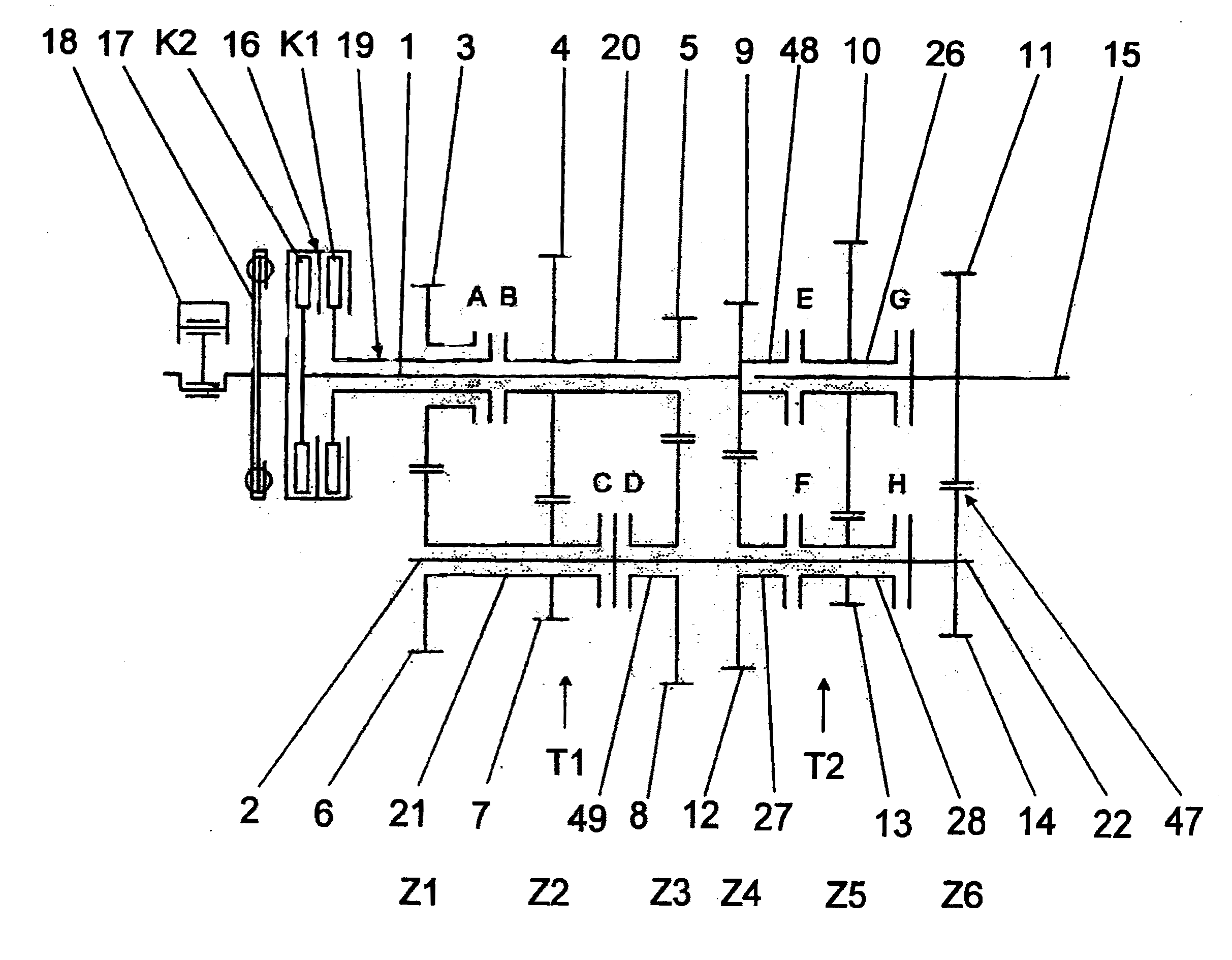
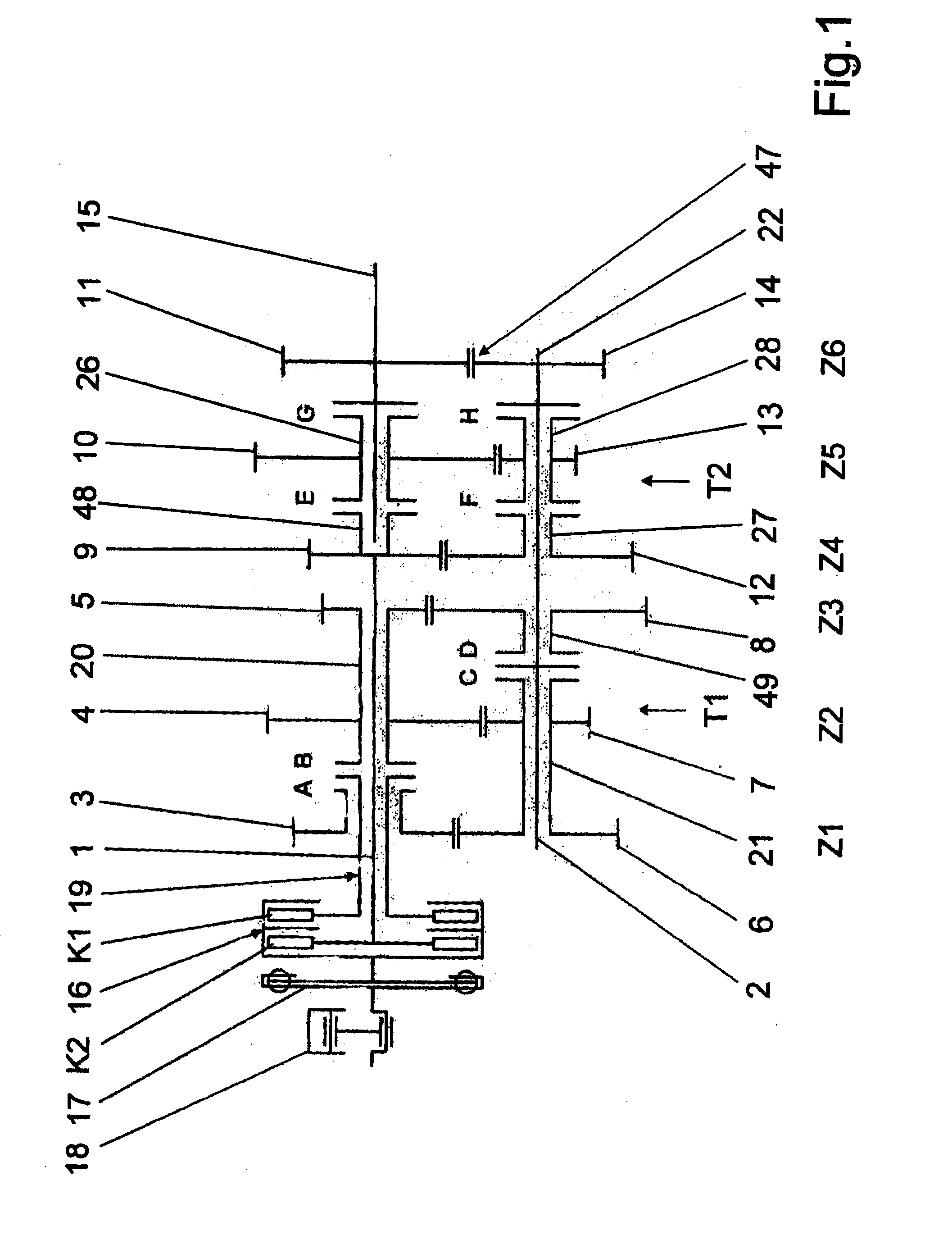
[0022]Through the arrangement of two, consecutively positioned winding transmissions, where each represents a sub-transmission with a gear group, an economically priced and easy to build double clutch transmission can be constructed, having more than seven forward gear positions, for instance having eight forward gear positions. The invention as such is especially advantageous for passenger cars with high torque and for utility vehicles.
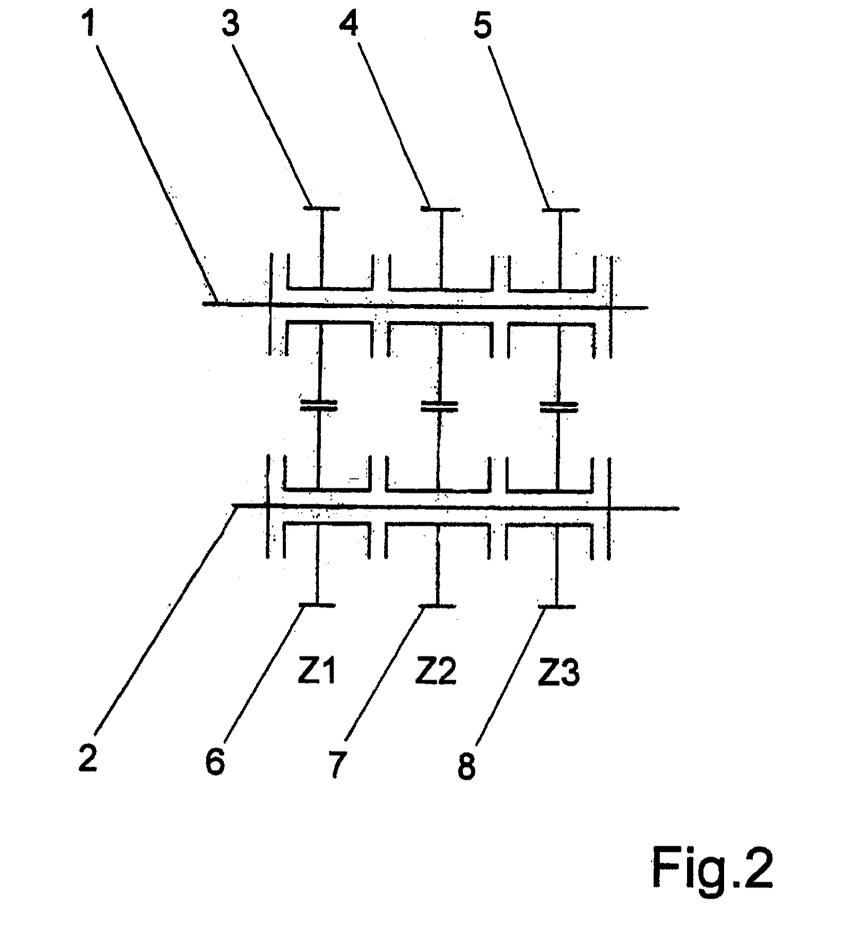
[0033]The transmission combination needs for the implementation of eight forward gear positions, in accordance with the winding design, a maximum of 2×3, or just six gear wheel stages in total, which has an economic effect as well as reducing the size and the weight. The combination demonstrates a high level of flexibility in the arrangement of the different gear wheel pairs and the choice of the individual gear ratios, so that numerous variations become available as the transmission's embodiment. A compromise is sought between a progressive and a geometric gradation of the transmission, with a, dependence on the application's shifting convenience and ride comfort, sufficient engine's use and transmission ratio spread. Thereby, the gear wheel pairs with either odd shift positions or even shift positions can selectively be assigned to both of the transmission input shafts.

Problems solved by technology

Disadvantageously, however, with this described transmission structure at least one gear wheel pair can be saved with the conventional intermediate transmission.
An increase to a higher number of gear positions than seven is not readily feasible, because of a complicated and elaborate construction and also a complicated flow of energy.

Method used


Image

  • Double clutch winding transmission
  • Double clutch winding transmission
  • Double clutch winding transmission

Examples


Embodiment Construction

[0083]Thus, FIG. 1 presents an eight gear position double clutch transmission for a vehicle in winding structure, having basically one first winding sub-transmission T1, positioned on the engine side of the double clutch transmission, and a second winding sub-transmission T2, positioned on the output side of the double clutch transmission.

[0084]The double clutch transmission comprises, as known in the art, a double clutch 16 which has two clutches K1, K2, which can be advantageously linked, via a vibration damper 17, with (shown symbolically with piston and crankshaft) a combustion engine 18. The double clutch 16 can be configured as a wet or a dry clutch and is preferably activated electro-mechanically or hydraulically. Conventional torsion vibration dampers as well as dual-mass fly wheels or hydraulic dampers are suitable for the vibration damper 17.

[0085]One clutch K1 is connected to the transmission input shaft 19, designed as hollow shaft, through which the first sub-transmissi...


PUM


Abstract

A double clutch winding transmission, having two sub-transmissions (T1, T2), coaxial transmission input shafts (1, 19), which are each coupled to a clutch (K1, K2), at least one counter shaft (2, 22) and a transmission output shaft (15) that is coaxially aligned with the transmission input shaft (1, 19). In at least one gear shift position, the flow of energy (L1 to L8) in the transmission winds through at least two meshing gear wheels (3 to 14), forming gear wheel levels (Z1 to Z6). The two sub-transmissions (T1, T2) are configured as two, consecutively positioned, single winding transmissions (W1, W2), each having at least four forward gear positions.

Description

[0001]This application is a National Stage completion of PCT / EP2007 / 061846 filed Nov. 5, 2007, which claims priority from German patent application serial no. 10 2006 054 281.9 filed Nov. 17, 2006.FIELD OF THE INVENTION[0002]The invention describes a Double Clutch Winding Transmission.BACKGROUND OF THE INVENTION[0003]Double clutch transmissions have already been in use in motor vehicles in gearbox transmissions, mainly in automatic transmission systems. They possess the distinction of operating under a nearly pull force free condition when shifting the gear position. Herewith, the accomplishments are more comfortable and fewer load changes during shifting, allowing at the same time a simultaneously, improved acceleration of the vehicle. A frequently used standard construction method utilizing coaxial drive shafts and their function is explained, for instance, in the DE 198 21 164 A1.[0004]Therein, two clutches which are located at the driving end and are for instance wet running pla...

Claims


Application Information

Patent Timeline
IPC IPC(8): F16H3/093F16H3/08
CPCF16H3/006F16H3/097F16H2003/0803F16H2003/0826Y10T74/19219F16H2200/006F16H2003/0807Y10T74/19228Y10T74/19233F16H2003/0933
Inventor GUMPOLTSBERGER, GERHARDRIEGER, WOLFGANG
Owner ZF FRIEDRICHSHAFEN AG
Learn More