
High speed wireless video transmission

a high-speed wireless video and video transmission technology, applied in the field of wireless communication, can solve the problems of few or no suitable wireless rf spectrum having a high enough bandwidth necessary lack of video quality and/or line-of-sight limitations, and inability to effectively carry encoded information

Inactive Publication Date: 2011-02-03
AZURE COMM
View PDF6 Cites 36 Cited by
  • Summary
  • Abstract
  • Description
  • Claims
  • Application Information

AI Technical Summary

Problems solved by technology

High definition television (HDTV), high definition Internet protocol streaming video (HD-IPTV) and other digital HD multimedia have historically been limited to wired transmission due to their extremely high data rate requirements.
Often HD multimedia encoded data rates range from 100 Mbps (million bits per second) to more than 2 Gbps (billion bits per second), which results in few or no suitable wireless RF spectrum having a high enough bandwidth necessary to effectively carry this encoded information.
Existing technology used for wireless-HD multimedia systems lack performance in range, video quality and / or have line-of-sight limitations.
These performance limitations result from adapting existing technologies, such as wireless local area networks (WLANs) or ultra-wide band (UWB) radio systems, to the vastly more rigorous bandwidth and performance requirements needed for HD multimedia signals.
Such existing solutions using UWB, WLAN and 60-GHz based technologies each have these and other drawbacks.
Due to the FCC's transmit power limitations for UWB signals however, the range is limited to about 10 meters.
Typically, such power limited UWB signals are inadequate when needing to penetrate through walls or obstructions or when requiring two-way communications.
Several factors, such as low bandwidths, large overhead signaling-to-payload ratio and interference with other nearby Wi-Fi devices, may limit maximum data rates of these radio systems to rates below what is necessary for full compatibility with HD multimedia standards.
The signal propagation characteristics at this frequency, however, limits reception to line-of-sight operations.
Typically, such signals are inadequate to penetrate through walls, do not provide two-way communications and use proprietary signaling protocols.
In addition, 60-GHz millimeter-wave radio systems are currently too expensive for incorporation into consumer electronics.

Method used


Image

  • High speed wireless video transmission
  • High speed wireless video transmission
  • High speed wireless video transmission

Examples


Embodiment Construction

[0027]In the following description, reference is made to the accompanying drawings, which illustrate several embodiments of the present invention. It is understood that other embodiments may be utilized and mechanical, compositional, structural, electrical, and operational changes may be made without departing from the spirit and scope of the present disclosure. The following detailed description is not to be taken in a limiting sense. Furthermore, some portions of the detailed description that follows are presented in terms of procedures, steps, logic blocks, processing, and other symbolic representations of operations on data bits that can be performed in electronic circuitry or on computer memory. A procedure, computer executed step, logic block, process, etc., are here conceived to be a self-consistent sequence of steps or instructions leading to a desired result. The steps are those utilizing physical manipulations of physical quantities. These quantities can take the form of e...


PUM


Abstract

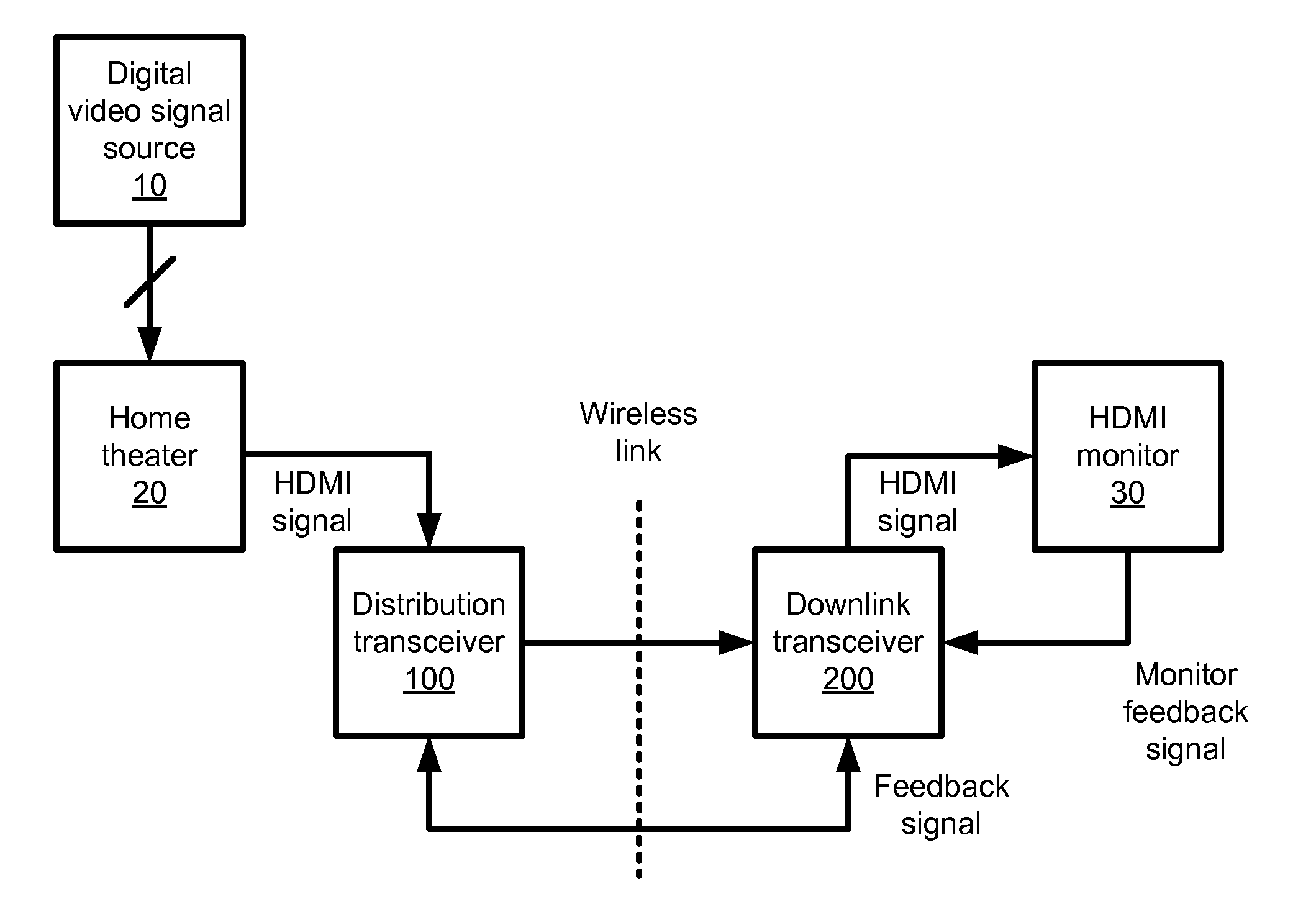
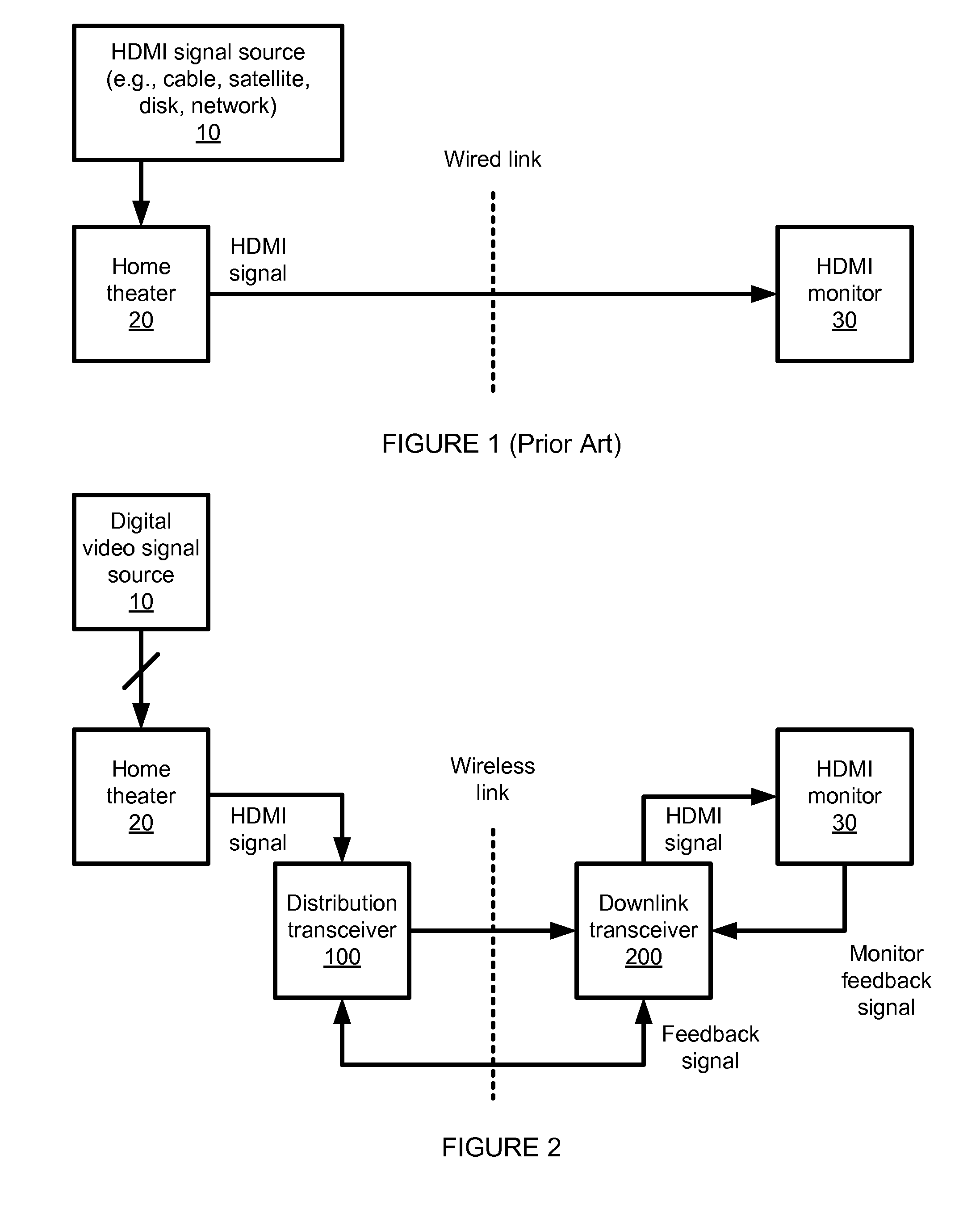
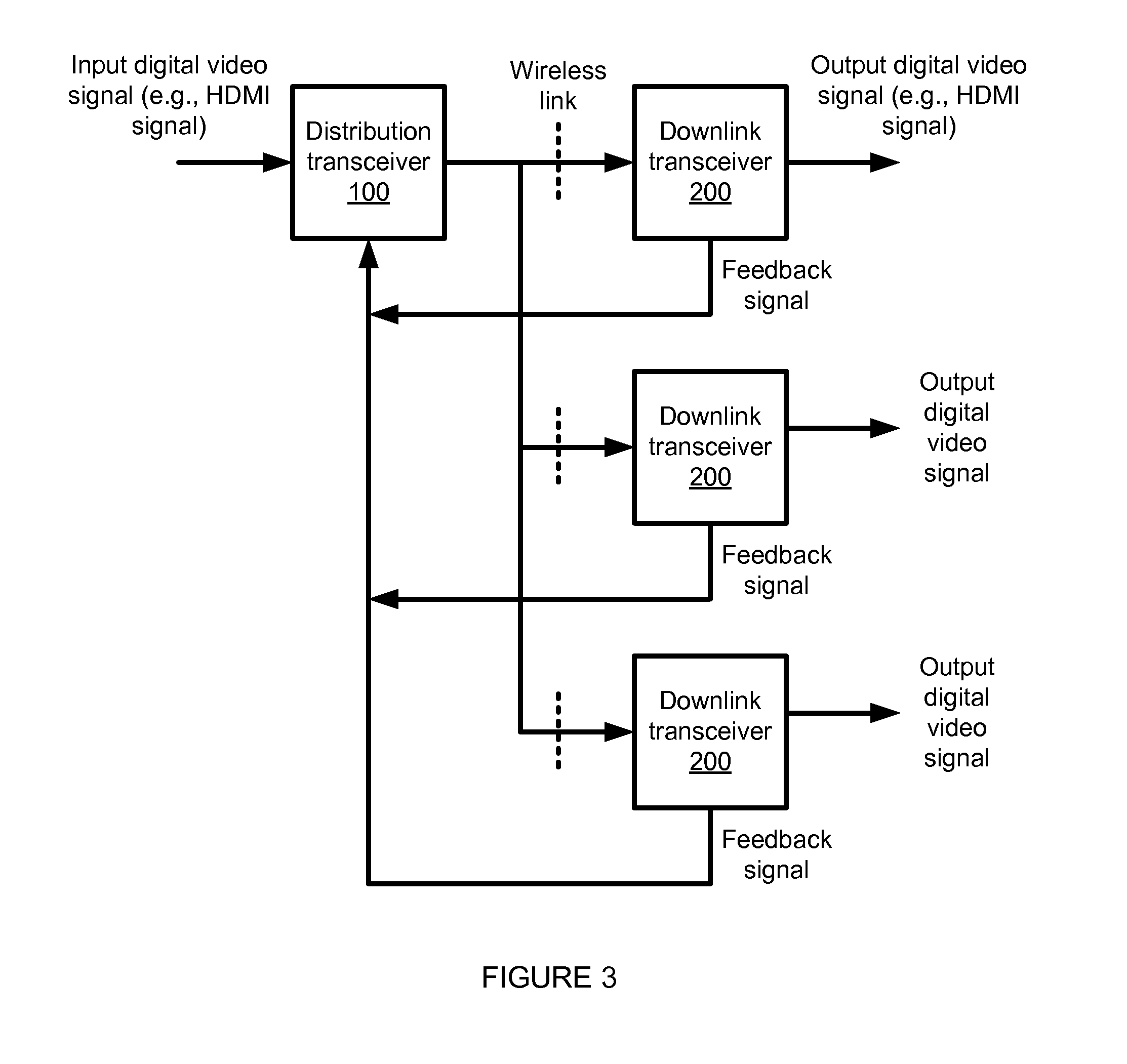
An implementation of a system and method for wirelessly communicating a digital video signal is provided. The system automatically compensates to maintain the received signal integrity as a wireless path for the transmitted digital video signal deteriorates. This method adjusts both the video compression rate and the modulation index in tandem to maintain a constant symbol rate.

Description

CROSS-REFERENCE TO RELATED APPLICATIONS[0001]Not Applicable.BACKGROUND OF THE INVENTION[0002]1. Field of the Invention[0003]The invention relates generally to wireless communications and more specifically to point-to-point or point-to-multipoint communication of wireless high definition digital video signals (e.g., wireless HDMI signals).[0004]2. Background of the Invention[0005]High definition television (HDTV), high definition Internet protocol streaming video (HD-IPTV) and other digital HD multimedia have historically been limited to wired transmission due to their extremely high data rate requirements. Often HD multimedia encoded data rates range from 100 Mbps (million bits per second) to more than 2 Gbps (billion bits per second), which results in few or no suitable wireless RF spectrum having a high enough bandwidth necessary to effectively carry this encoded information.[0006]Existing technology used for wireless-HD multimedia systems lack performance in range, video quality ...

Claims


Application Information

Patent Timeline
Patent Type & Authority Applications(United States)
IPC IPC(8): H04N7/173H04N5/40H04N7/12
CPCH04L69/04H04N21/43637
Inventor BERTONIS, JAMES G.GIESE, GEOFFREY L.
Owner AZURE COMM
Learn More