
Fuel cell system

Active Publication Date: 2011-02-03
TOYOTA JIDOSHA KK
View PDF7 Cites 10 Cited by
  • Summary
  • Abstract
  • Description
  • Claims
  • Application Information

AI Technical Summary

Benefits of technology

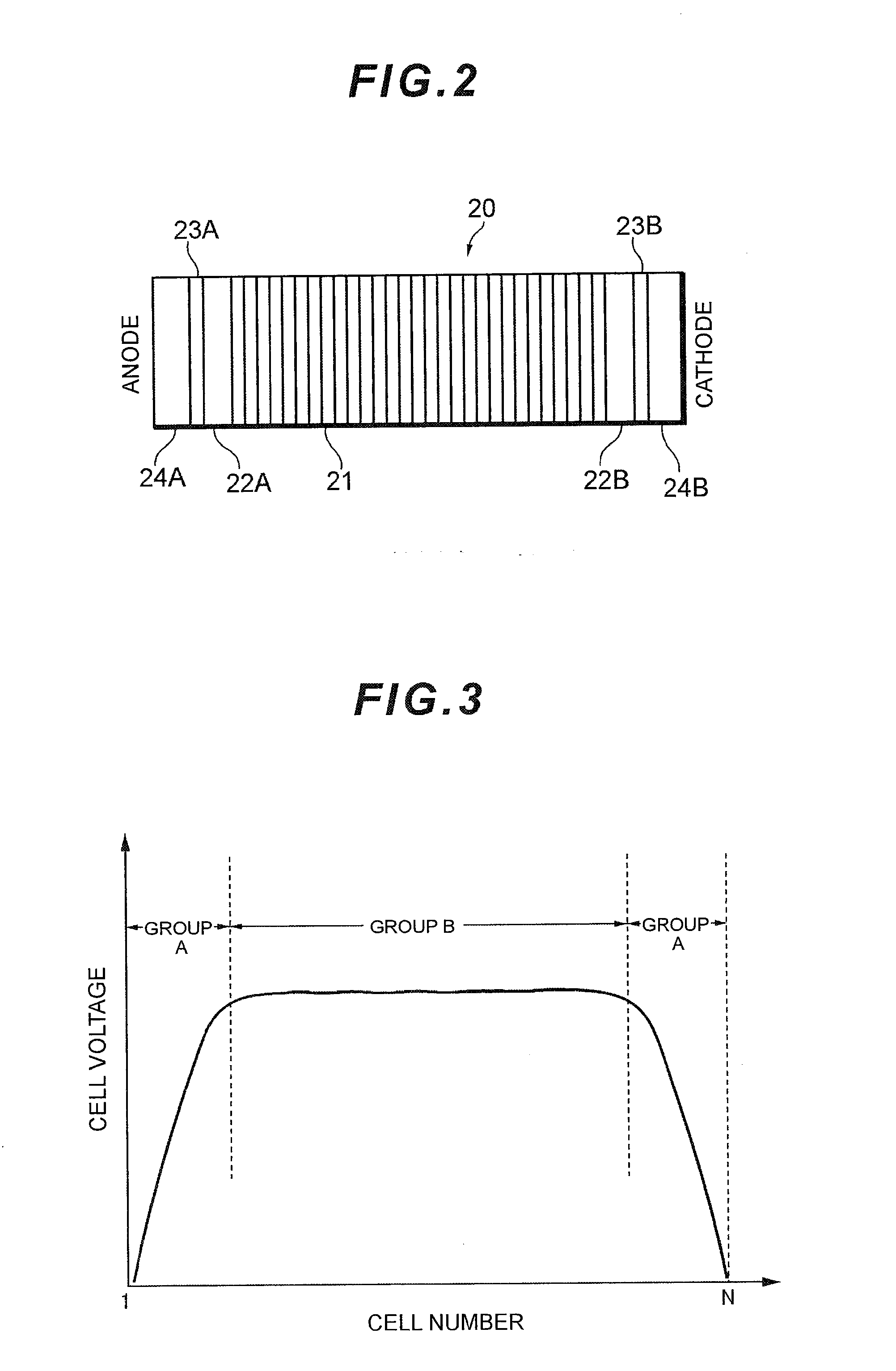
[0008]In the first cell group placed at each end of the cell stack (an anode pole side end and a cathode pole side end), as compared with the second cell group placed at substantially the center of the cell stack, a temperature difference is easily made in the cell, between the cells or between the poles, and the lowering of the cell voltage due to a deficiency in the supply of a reactant gas, caused by flooding or the like, easily occurs. In particular, at a low-temperature start, there is a high necessity of avoiding a cell damage due to the deficiency in the supply of a fuel gas, and hence the cell voltage management of the first cell group needs to be stringently performed.

Problems solved by technology

Therefore, when the same cell voltage recovery processing is executed for all the cells, the cell voltage recovery processing is executed more than necessary, or an output is sometimes excessively limited to lower an operation efficiency.

Method used


Image

  • Fuel cell system
  • Fuel cell system
  • Fuel cell system

Examples


Embodiment Construction

[0020]Hereinafter, an embodiment of the present invention will be described with reference to the drawings.

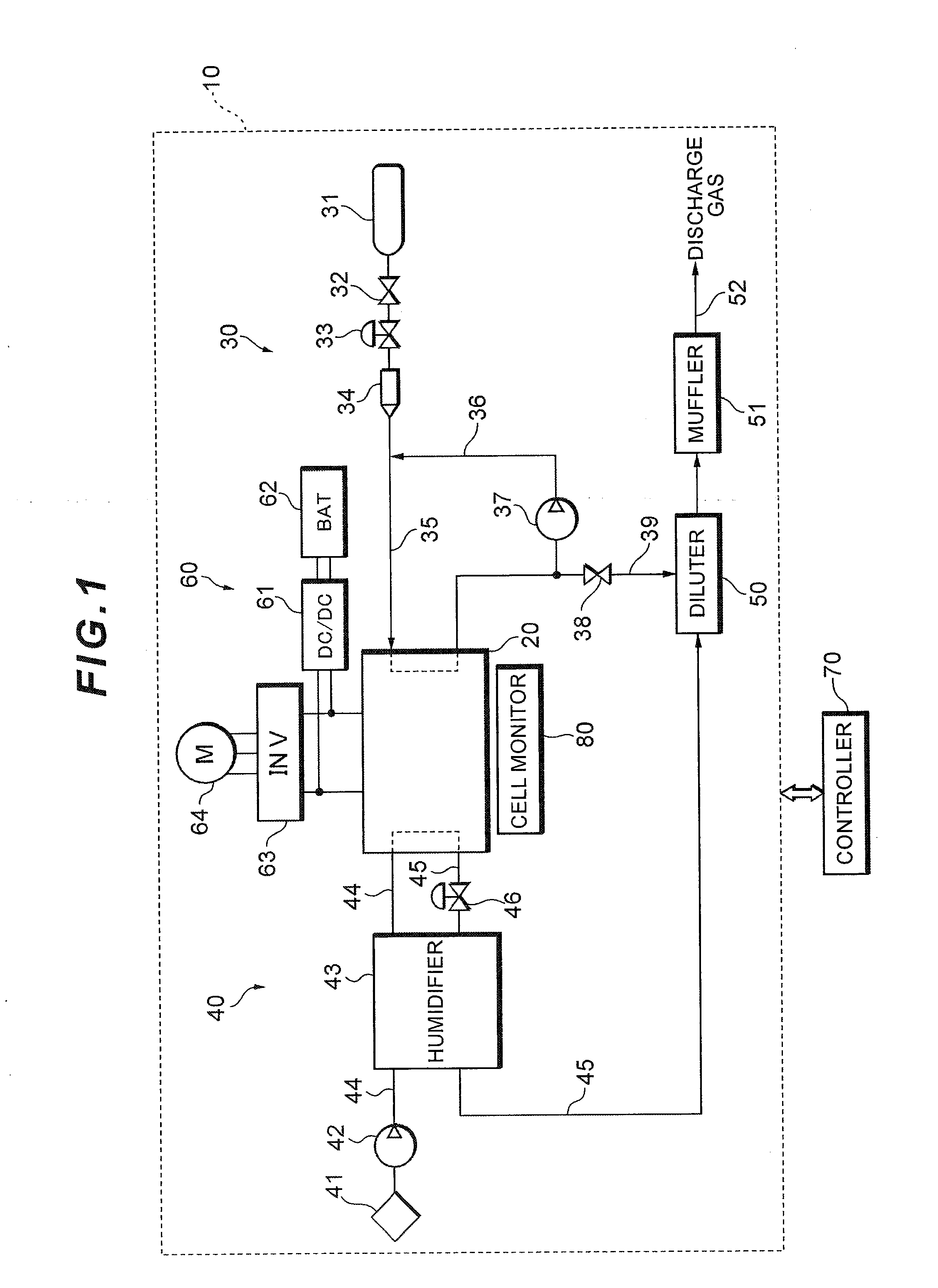
[0021]FIG. 1 shows a system constitution of a fuel cell system 10 which functions as a car-mounted power source system of a fuel cell vehicle.

[0022]The fuel cell system 10 includes a fuel cell stack 20 which receives a supplied reactant gas (an oxidizing gas and a fuel gas) to generate a power; a fuel gas piping system 30 which supplies a hydrogen gas as the fuel gas to the fuel cell stack 20; an oxidizing gas piping system 40 which supplies air as the oxidizing gas to the fuel cell stack 20; a power system 60 which controls the charging / discharging of the power; and a controller 70 which generally controls the whole system.

[0023]The fuel cell stack 20 is a solid polymer electrolyte type cell stack in which a large number of cells are stacked in series. Each cell has a cathode pole on one face of an electrolytic film constituted of an ion exchange membrane and an anode pole on ...


PUM


Abstract

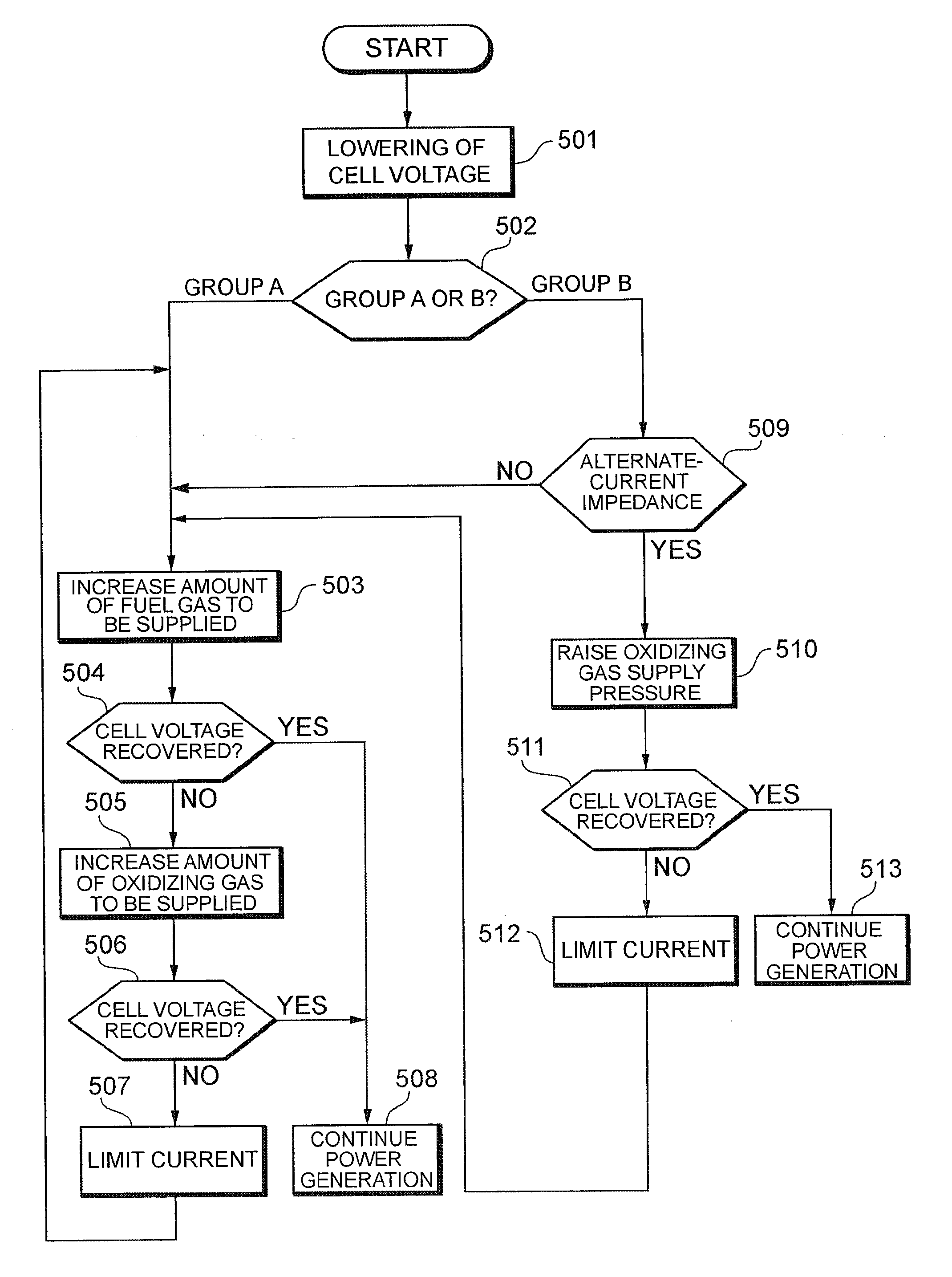
A fuel cell system has a fuel cell stack and a controller. The fuel cell stack is formed by stacking cells. The controller executes first cell voltage recovery processing when the cell voltage of a first cell group, placed at each end of the fuel cell stack, is below a first lower limit voltage threshold and executes second cell voltage recovery processing, which is different from the first cell voltage recovery processing, when the cell voltage of a second cell group, placed at substantially the center of the fuel cell stack, is below a second lower limit voltage threshold.

Description

TECHNICAL FIELD[0001]The present invention relates to a fuel cell system. More particularly, it relates to cell voltage recovery processing of a fuel cell stack.BACKGROUND ART[0002]In recent years, as part of efforts against environmental problems, low-pollution cars have been developed, and the cars include a fuel cell vehicle in which a fuel cell stack is used as a car-mounted power source. The fuel cell stack has a stack structure in which a plurality of cells are stacked in series, and each cell has a membrane-electrode assembly in which an anode pole is arranged on one face of an electrolytic film, whereas a cathode pole is arranged on the other face thereof. A fuel gas and an oxidizing gas are supplied to the membrane-electrode assembly to cause an electrochemical reaction, and chemical energy is converted into electric energy. Above all, a solid polymer electrolyte type fuel cell stack in which a solid polymer film is used as an electrolyte can easily be made compact at a low...

Claims


Application Information

Patent Timeline
IPC IPC(8): H01M8/04
CPCH01M8/04552H01M8/04641H01M8/04671H01M8/04753H01M8/0488Y02E60/50H01M8/0494H01M8/04947H01M8/04955H01M8/241H01M8/0491H01M8/04H01M8/24
Inventor NONOBE, YASUHIRO
Owner TOYOTA JIDOSHA KK
Learn More