Arrangement for axially securing rotating blades in arotor, and gas turbine having such an arrangement

Inactive Publication Date: 2011-02-03
SIEMENS AG
View PDF3 Cites 5 Cited by
  • Summary
  • Abstract
  • Description
  • Claims
  • Application Information

AI Technical Summary

Benefits of technology

[0009]It is the object of the present invention to disclose an alternative arrangement for securing the sealing elements against a rotating displacement in the circumferential direction, in which the installation and removal times are improved. The provision of a gas turbine with such an arrangement is a further object of the invention.
[0012]By using a blocking element which engages in the opening of the sealing element and is fastened on the end face on the shaft collar by means of caulking which plastically deforms the blocking element, a particularly reliable and simple axial securing of the sealing element against displacement in the circumferential direction can be achieved. Furthermore, installation is to be accomplished quickly and simply. For this purpose, the blocking element is to be plastically deformed on the end face with a suitable caulking tool, for example a tool in the style of a hammer and chisel, so that it abuts in the recess under tension. As a result, an exceptionally reliable frictional engagement between the wall of the recess and the blocking element is brought about, which reliably prevents the unwanted loosening of the blocking element during operation of the gas turbine. For removing the blocking element, the deformed region of the blocking element can be removed by grinding and in this way the frictional engagement is loosened for removal.
[0013]In addition, with the construction according to the invention the slots which were provided for fastening the locking plate on the sealing element and previously weakened the sealing element are dispensed with. The rigidity of the sealing element is subsequently further increased, also its sealing effect.
[0016]According to an alternative development of the invention, the recess which accommodates the blocking element is open as seen in the radially outward direction. In this case, the blocking element which is inserted therein can be plastically deformed on the circumferential side, with regard to the rotor, instead of the end-face deformation. As long as provision is then still made for pockets which are additionally arranged in the sidewalls of the recess on the circumferential side, into which parts of the deformed material of the blocking element can deflect, a form-fit for positional locking of the blocking element can additionally also be provided in addition to the caulking of the blocking element. As a result of this, the blocking element is especially reliably safeguarded against loss.
[0017]According to a further advantageous development, the recess, extending in the axial direction of the rotor, is arranged in the side surface of the shaft ring in such a way that it extends right into the encompassing slot. Weakening of the shaft collar or of a rotor disk which preferably forms the shaft collar is avoided in this case. Therefore, the opening which is provided on the sealing element is then provided on the radial inner end of the sealing element. This region of the sealing element heats up the least during operation so that the rigidity and the temperature resistance of the sealing element are not impaired as a result of the opening.

Problems solved by technology

Furthermore, the slots which are provided for accommodating the metal strips in the sealing plates weaken the said sealing plates.

Method used


Image

  • Arrangement for axially securing rotating blades in arotor, and gas turbine having such an arrangement
  • Arrangement for axially securing rotating blades in arotor, and gas turbine having such an arrangement
  • Arrangement for axially securing rotating blades in arotor, and gas turbine having such an arrangement

Examples


Embodiment Construction

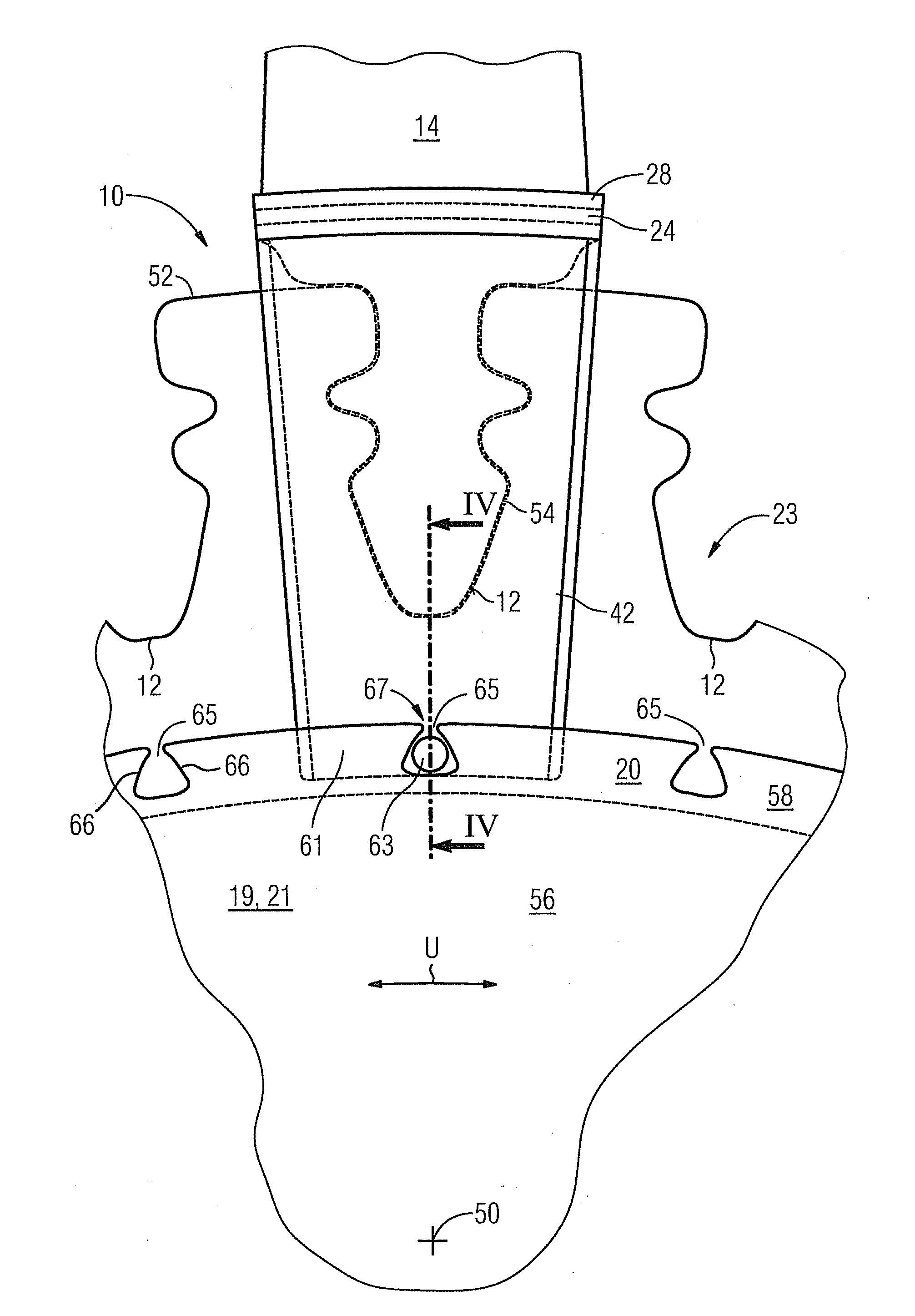
[0025]FIG. 3 shows a detail of the end-face plan view of the shaft collar 21, which is formed by a rotor disk 19, of a rotor 23 of a gas turbine. The rotor 23, which is rotatable around the rotational axis 50, has rotor blade retaining slots 12 which are distributed on its outer periphery 52 along the circumference U and extend in the axial direction, into which slots a rotor blade 14, with a blade root 54 which is constructed corresponding to the rotor blade retaining slot 12, in each case can be inserted. A rotor blade 14 is already inserted in the rotor blade retaining slot 12 which is shown in the middle in FIG. 3. As in the case of the prior art which is shown in FIG. 1 and FIG. 2, a projection 58 or widening, with a radially outwardly open encompassing slot 20 therein, which extends in the axial direction, is arranged on an end face of the rotor disk 19 or on an end-face side surface 56 of the shaft collar 21. The encompassing slot 20 for example is arranged radially further i...


PUM


Abstract

An arrangement for axial locking of rotating blades in a rotor is provided. The arrangement includes a shaft collar, a projection, plate-like sealing elements, and a blocking element. The sealing elements are provided for axially securing the rotating blades. At least one sealing element has an opening for securing the sealing elements against displacement in the circumferential direction. The blocking element is inserted in a recess from the end side of the shaft collar and blocks the displacement path of the sealing element. In order for the blocking element to be secured against unintentional releasing, the blocking element is fastened on the rotor disk using plastic deformation.

Description

CROSS REFERENCE TO RELATED APPLICATIONS[0001]This application is the US National Stage of International Application No. PCT / EP2008 / 053271, filed Mar. 19, 2008 and claims the benefit thereof. The International Application claims the benefits of European Patent Office application No. 07007088.3 EP filed Apr. 4, 2007, both of the applications are incorporated by reference herein in their entirety.FIELD OF INVENTION[0002]The invention refers to an arrangement for axial locking of rotor blades in a rotor, with a shaft collar, on the outer periphery of which provision is made for rotor blade retaining slots which extend in the axial direction of the rotor and in which rotor blades, with blade roots which correspond to the rotor blade retaining slot, are arranged in each case, with a projection which is arranged on an end-face side surface of the shaft collar in the region of the retaining slots, in which projection a radially outwardly open encompassing slot is provided and with radially ...

Claims


Application Information

Patent Timeline
IPC IPC(8): F01D5/30
CPCF05B2260/301F01D5/3015
Inventor ENGLE, DARREN T.
Owner SIEMENS AG
Why Eureka
Try Eureka