Construction machine

Active Publication Date: 2011-02-03
KOBELCO CONSTR MASCH CO LTD
View PDF5 Cites 16 Cited by
  • Summary
  • Abstract
  • Description
  • Claims
  • Application Information

AI Technical Summary

Benefits of technology

[0012]According to the present invention there is provided a construction machine which permits a guard member to operate effectively against an external force acting in a direction to strip off a cab from an upper frame, while making the most of the shock absorbing function of a anti-vibration mount.
[0014]Thus, according to the present invention, in the construction machine wherein the cab is mounted on the upper frame through the anti-vibration mount, the guard member for protecting the cab in the event of a roll over of the construction machine is attached to the cab, and the lower end of the front portion of the guard member which covers the front face portion of the cab is fixed to the front end portion of the upper frame by the fixing mechanism which permits movement of the cab created in both vertical and horizontal directions by the anti-vibration mount. Therefore, while making the most of the shock absorbing function of the anti-vibration mount, an external force acting in a direction to strip off the cab from the upper frame is received by the fixing mechanism, whereby it is possible to prevent disengagement of the cab.
[0015]Since the fixing mechanism is provided between the guard member and the upper frame which are easy to ensure a high strength, the cab disengagement preventing effect is further ensured.
[0022]In this case, the fixing mechanism includes the shaft extending from the upper frame side to the guard member side and provided movably in the vertical direction together with the guard member and the stopper fixed by the upper frame side to limit the amount of movement of the shaft to a magnitude corresponding to the shock absorbing stroke of the anti-vibration mount. Therefore, the structure of the fixing mechanism is simplified and easy to install.
[0023]In this case, since the internal thread body is fixed to the guard member side and the screw shaft is screwed into the internal thread body from the upper frame side, the installation of the fixing mechanism becomes extremely easy.
[0024]Moreover, since the sleeve fitted on the screw shaft is pressed to be in contact with the internal thread body with the tightening force of the screw shaft to produce an axial force for the prevention of loosening of the screw shaft, it is possible to prevent the screw shaft from becoming loose due to vibration or the like and hence possible to keep the clearance constant.

Problems solved by technology

On the other hand, in the structure of Patent Document 4 wherein the guard member is attached to the upper frame, this structure is effective in point of preventing disengagement of the cab 4, but in a construction machine provided with the anti-vibration mounts 9, as shown in FIG. 8, there arises drawback that the shock absorbing function of the mounts 9 is killed by the guard member.

Method used


Image

  • Construction machine
  • Construction machine
  • Construction machine

Examples


Embodiment Construction

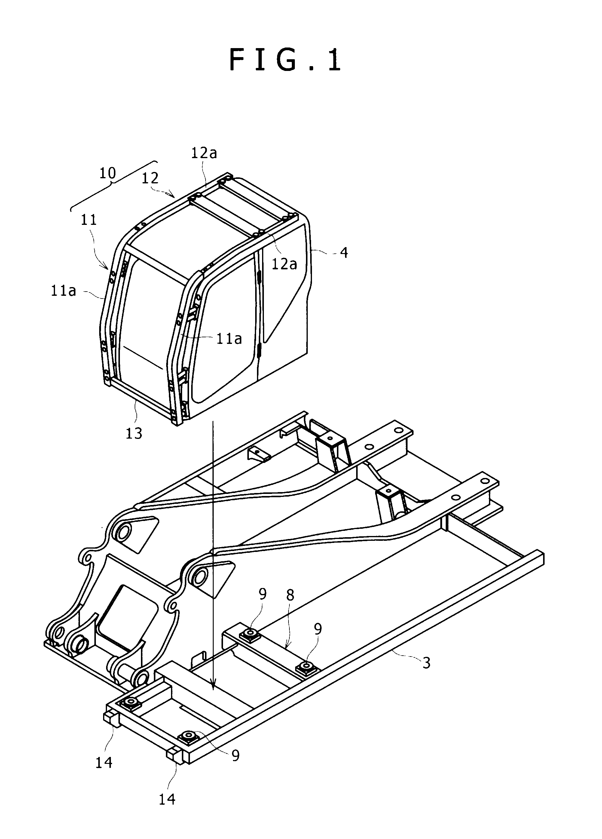
[0033]An embodiment of the present invention will be described below with reference to FIGS. 1 to 6.

[0034]In this embodiment a description will be given assuming that a hydraulic excavator is the construction machine to which the present invention is applied to match the description of the related art. In the following embodiment the same portions as in FIGS. 7 and 8 will be denoted by the same reference numerals as in those figures and repeated explanations thereof will be omitted.

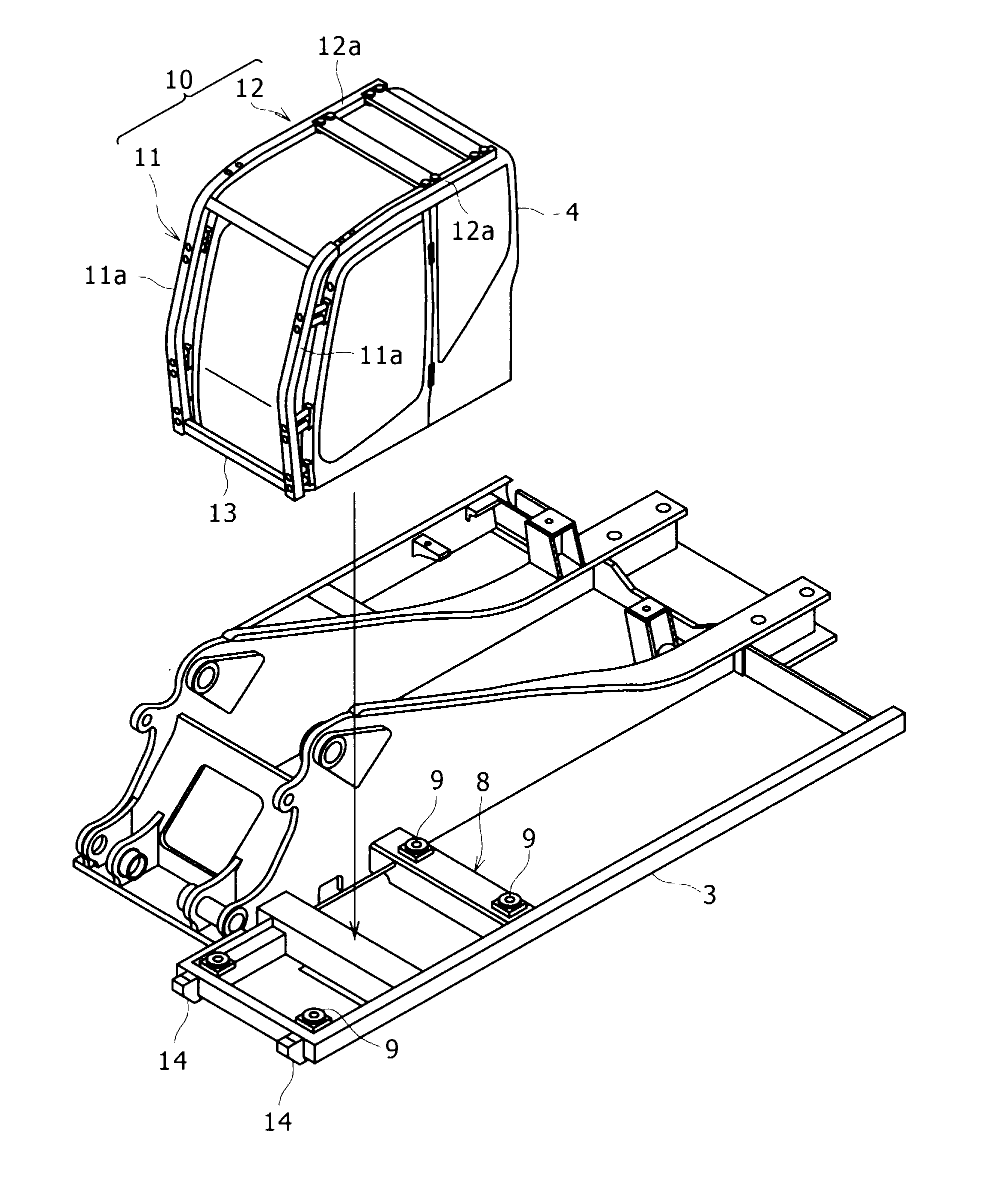
[0035]A cab mounting section 8 is provided for a left front portion of an upper frame 3 and a cab 4 is mounted on the cab mounting section 8 while being supported elastically at four corners by anti-vibration mounts 9.

[0036]A guard member 10 is attached to the cab 4 to protect the cab in the event of a roll over of the construction machine.

[0037]The guard member 10 is made up of a front portion 11 which covers both right and left sides of a front face portion of the cab and a rear portion 12 extending bac...


PUM


Abstract

In a construction machine wherein a cab is mounted on an upper frame of an upper rotating body through an anti-vibration mount, a guard member for protecting the cab in the event of a roll over of the construction machine is mounted so as to extend from a front face portion to a ceiling of the cab, and a lower end of a front portion of the guard member which front portion covers the front face portion of the cab is fixed to a front end portion of the upper frame by a fixing mechanism which permits movement of the cab created in both vertical and horizontal directions by the anti-vibration mount.

Description

BACKGROUND OF THE INVENTION[0001]1. Field of the Invention[0002]The present invention relates to a construction machine having an improved structure for protecting a cab and ensuring an intra-cab operator space in the event of a roll over of the construction machine.[0003]2. Description of the Related Art[0004]In a hydraulic excavator, as shown in FIG. 7, an upper rotating body 2 is mounted on a lower traveling body 1 of a crawler type so as to be rotatable about an axis O which is vertical to the ground, and a cab 4 as an operating room for an operator to get thereon is installed on either the right or the left side (the left side in the following description) of an upper frame 3 of the upper rotating body 2. Further, a working attachment 6 including a boom 5 is mounted to be raised and lowered to the right of the cab 4.[0005]In FIG. 7, the numeral 7 denotes a counter weight provided at a rear end portion of the upper frame 3.[0006]As shown in FIG. 8, the upper frame 3 is provided ...

Claims


Application Information

Patent Timeline
IPC IPC(8): B62D33/06
CPCB62D33/0604E02F9/166E02F9/163B62D33/0617
Inventor YAMAMOTO, KEIJIKOBAYASHI, KAZUAKIMURAKAMI, YOSHIAKI
Owner KOBELCO CONSTR MASCH CO LTD
Why Eureka
Try Eureka