
Hollow fiber membrane module and puller used therefor

a technology of hollow fiber membrane module and puller, which is applied in the direction of membranes, filtration separation, separation processes, etc., can solve the problems of high possibility, adversely affected by heat, and their permeability to be declined, and achieve the effect of easy pulling ou

Inactive Publication Date: 2011-02-03
KOLON IND INC
View PDF6 Cites 5 Cited by
  • Summary
  • Abstract
  • Description
  • Claims
  • Application Information

AI Technical Summary

Benefits of technology

[0026]A hollow fiber membrane module according to the present invention and a puller used therefor has the following advantages.
[0027]Each individual hollow fiber membrane module can be easily pulled out from a filtering apparatus provided with a plurality of hollow fiber membrane modules if it is required to be replaced or repaired. In this case, even though the plurality of hollow fiber membrane modules are maintained in close contact with one another, the individual hollow fiber membrane module to be replaced or repaired can be easily pulled out from the filtering apparatus without disassembling the filtering apparatus.

Problems solved by technology

Furthermore, since the separation method using a membrane does not require a heating process, a membrane can be used with microorganism which is useful for separation process but may be adversely affected by heat.
However, when the submerged-type hollow fiber membrane module is used to treat wastewater, the solids in the wastewater fouls the membranes causing their permeability to be declined as the water treatment is processed.
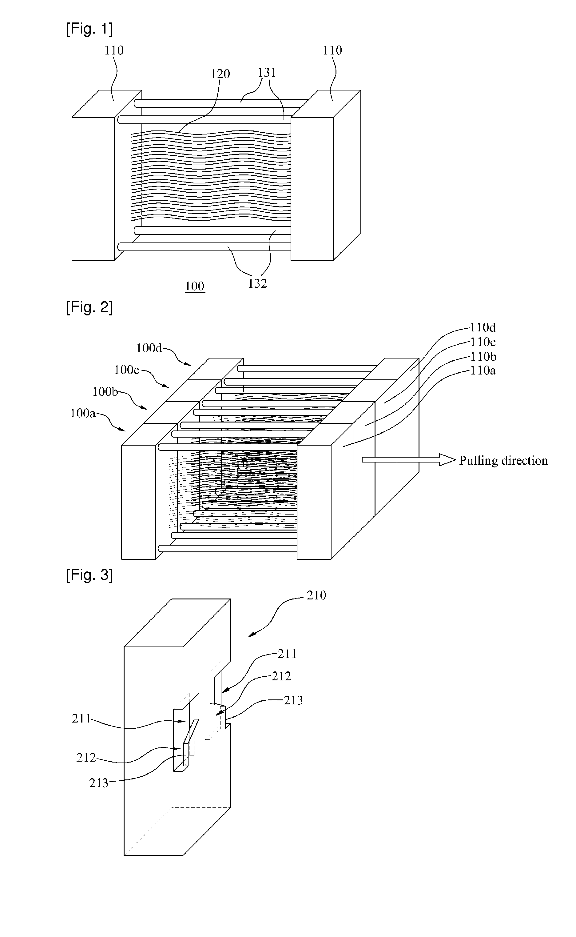
Furthermore, there is a high possibility that the hollow fiber membrane modules 100a, 100b, 100c, and 100d are damaged by their collision.
Furthermore, a large-sized hollow fiber membrane module according to a recent trend requiring a large water-treatment capacity may cause more difficulty in individually pulling out each individual hollow fiber membrane module from the filtering apparatus.

Method used


Image

  • Hollow fiber membrane module and puller used therefor
  • Hollow fiber membrane module and puller used therefor
  • Hollow fiber membrane module and puller used therefor

Examples


Embodiment Construction

[0037]Reference will now be made in detail to the preferred embodiments of the present invention, examples of which are illustrated in the accompanying drawings. Wherever possible, the same reference numbers will be used throughout the drawings to refer to the same or like parts.

[0038]Hereinafter, a hollow fiber membrane module according to the present invention and a puller used therefor will be explained with reference to the accompanying drawings.

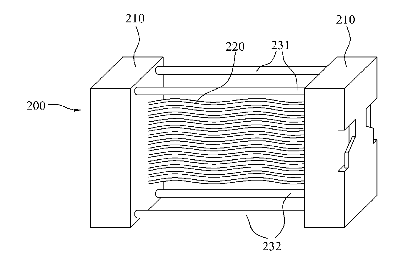
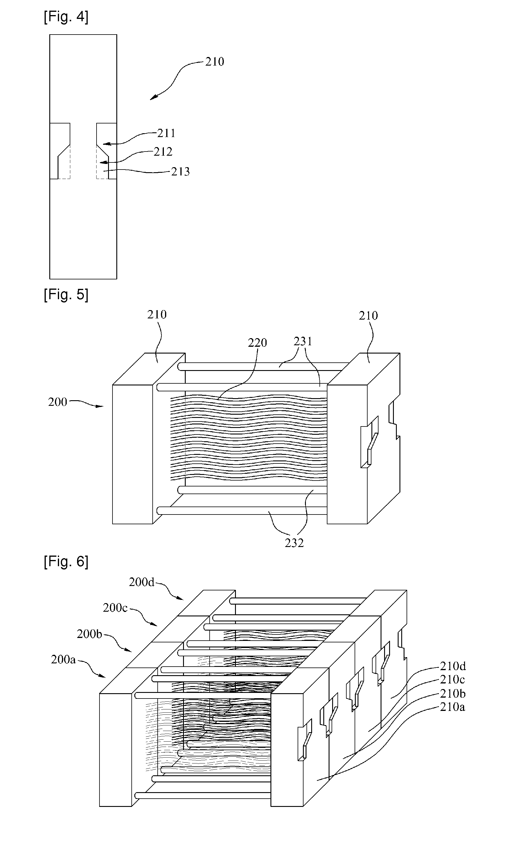
[0039]FIG. 3 is a perspective view illustrating a header in a hollow fiber membrane module according to one embodiment of the present invention, and FIG. 4 is a lateral view thereof. FIG. 5 is a perspective view illustrating a hollow fiber membrane module according to one embodiment of the present invention. FIG. 6 is a perspective view illustrating a packing structure of hollow fiber membrane modules according to one embodiment of the present invention.

[0040]As shown in FIGS. 3 to 6, a hollow fiber membrane module 200 according to the p...


PUM

PropertyMeasurementUnit
heightaaaaaaaaaa
shapeaaaaaaaaaa
pulling-forceaaaaaaaaaa

Abstract

A hollow fiber membrane module (200) and a puller (300) used therefore is disclosed, wherein each individual hollow fiber membrane module can be easily pulled out from a filtering apparatus provided with a plurality of hollow fiber membrane modules if it is required to be replaced or repaired. At this time, the hollow fiber membrane module (200) comprises a hollow fiber membrane (220); and at least on header (210) to which the hollow fiber membrane is potted, wherein the header (210) includes a first lateral side to which the hollow fiber membrane is potted and a second lateral side opposite to the first lateral side; and wherein an engaging plate (213) is formed at the second lateral side. Also, the puller (300) comprises a main body (310) and a hooking member (320), extending from an end of the main body, formed in a shape suitable for being caught in the engaging plate (213).

Description

TECHNICAL FIELD[0001]The present invention relates to a hollow fiber membrane module and a puller used therefor, and more particularly, to a hollow fiber membrane module and a puller used therefor, wherein each individual hollow fiber membrane module can be easily pulled out from a filtering apparatus provided with a plurality of hollow fiber membrane modules if it is required to be replaced or repaired.BACKGROUND ART[0002]A separation method using a membrane has lots of advantages over the method based on heating or phase-changing. Among the advantages is high reliability of water treatment since the water purity required can be easily and stably satisfied by adjusting the size of the pores of a membrane. Furthermore, since the separation method using a membrane does not require a heating process, a membrane can be used with microorganism which is useful for separation process but may be adversely affected by heat.[0003]Among the membrane employing separation methods is a method us...

Claims


Application Information

Patent Timeline
Patent Type & Authority Applications(United States)
IPC IPC(8): B01D63/02B01D65/00
CPCB01D63/02B01D63/04Y10T29/49822B01D2313/21B01D2313/90B01D65/00B01D63/031B01D69/08
Inventor LEE, KWANG-JIN
Owner KOLON IND INC
Learn More