
Solar power plant

a solar power plant and solar array technology, applied in photovoltaics, solar heat collectors for particular environments, solar radiation concentration, etc., can solve the problems of arrays that are mechanically complicated and costly, large space requirements for solar arrays, and low energy yield per required unit surface area, so as to achieve better utilization, save space, and produce more energy

Inactive Publication Date: 2011-02-03
BUCHEL ARTHUR R +1
View PDF2 Cites 15 Cited by
  • Summary
  • Abstract
  • Description
  • Claims
  • Application Information

AI Technical Summary

Benefits of technology

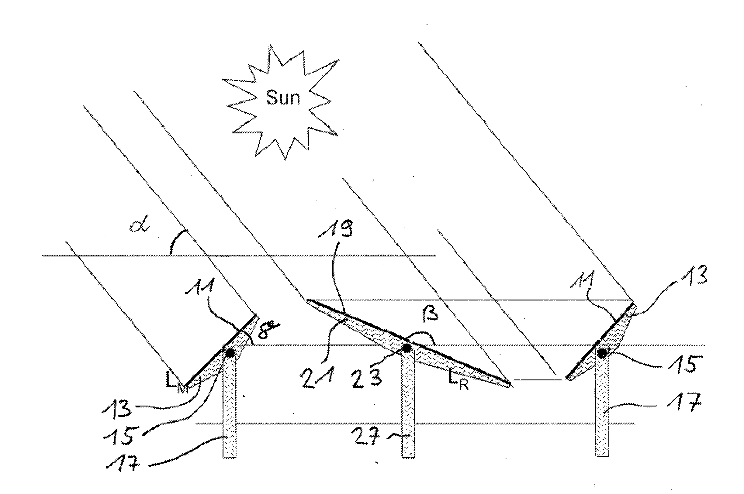
[0016]A solar array according to the invention provides reflector elements at a distance from the solar modules, that by means of a first tracking device the solar modules may be tracked about a first rotational axis, and by means of a second tracking device independent from the first tracking device the reflector elements may be tracked about a second rotational axis of the solar trajectory over the course of a day, so that solar radiation striking the reflector elements may be at least partially projected onto the receiver surface of an adjacent solar module. Compared to the conventional variants described at the outset, the present invention has the advantage that a higher annual energy yield per unit photovoltaic module surface area is achieved than for conventional fixed or tracked module systems. This results in reduced power generation costs. A further advantage is that a higher annual energy yield per m2 of total array surface area is achieved, since in particular at steeper solar radiation angles (higher solar altitude) a greater proportion of the solar energy is projected onto the photovoltaic modules, and at that location is converted to electrical energy. Overall, this also results in improved cost efficiency for the array, since tracked reflector elements may be installed due to the low additional cost. The reflector elements also result in lower impingement of the ground area between the solar modules with solar radiation (shading). However, the shading caused by the reflector elements may also provide further advantages, depending on the utilization, for example for landscaping or shading of parking areas or roofs. At high wind speeds the configuration according to the invention has the advantage that the solar modules as well as the reflector elements may be oriented in such a way that the surface area on the array exposed to wind is minimal, resulting in high robustness and also allowing the mechanical design of the components to be optimized.
[0017]The reflectors may preferably be swiveled about at least one axis. This has the advantage that the reflectors may be oriented as a function of the solar altitude. The solar modules may also advantageously be pivotable about one axis, allowing swiveling of the solar modules and tracking of the solar trajectory. The energy yield may be maximized in this manner. In principle, the tracking devices may allow tracking about one or two axes. At least a third tracking device is also preferably provided to allow mutual swiveling of the solar modules and of the reflector elements about a further respective axis. This further axis is advantageously perpendicular to the respective swivel axes of the solar modules and reflector elements. In that case a third tracking device is sufficient when the solar modules and reflector elements are situated on a common supporting framework. However, in principle it is possible to provide separate (third and fourth) tracking devices about a further axis for swiveling of the solar modules and reflector elements.
[0018]It is advantageous to provide multiple rows of solar modules situated behind or adjacent to one another, and multiple rows of reflector elements. Each row of reflector elements is then located at a distance from the row of solar modules. Symmetrically configured rows of solar modules and reflector elements have the advantage that the space requirements are small, and tracking of the solar modules and reflector elements is possible with little complexity. It is practical for the reflector of the reflector element to allow bundling of the incident solar radiation. This has the advantage of increased efficiency of the solar array according to the invention.

Problems solved by technology

Solar arrays have a large space requirement due to the great distances between the modules.
Furthermore, the energy yield per required unit surface area is low.
However, these arrays are mechanically complicated and costly, and also have a low energy yield per required unit surface area.
However, module utilization is not optimal in such a configuration, since the grazing solar radiation strikes the module surface only at a very flat angle.
A further disadvantage is that for a flat angle of incidence the radiation is introduced less efficiently into the solar module.
However, a disadvantage of the solar array of US 2002 / 0075579 is that the curved reflector elements are relatively costly to manufacture.
A further disadvantage is that tracking of the solar array according to the solar altitude requires a relatively complex mechanism.
However, at high light concentrations this system requires specialized solar cells with appropriate cooling and complex tracking of the reflectors as a function of the particular solar altitude.

Method used


Image

  • Solar power plant
  • Solar power plant
  • Solar power plant

Examples


Embodiment Construction

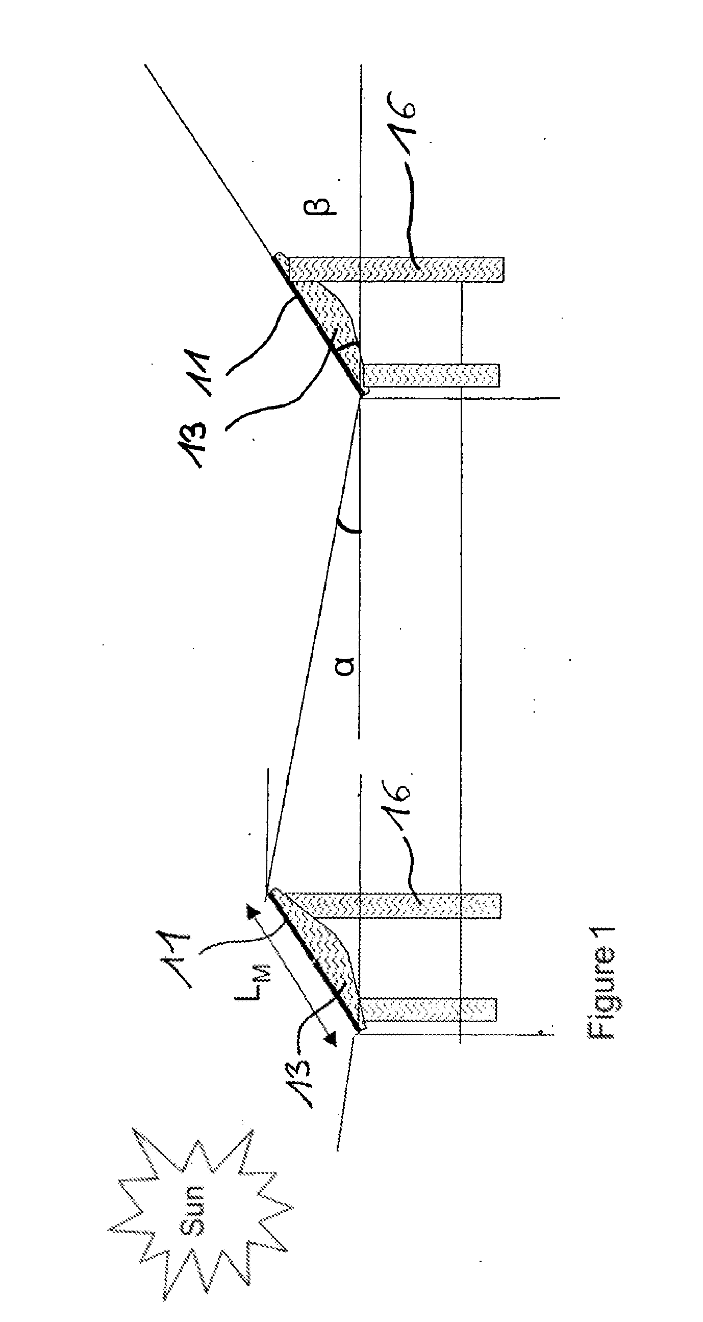
[0046]FIG. 1 schematically shows a known configuration of a solar array having a plurality of solar modules 11 situated at a fixed distance from one another. The solar modules 11 are provided on holders 13 which in turn are mounted on poles 16. The solar modules 11 must be set up at a distance from one another which avoids shading of an adjacent solar module to the greatest extent possible at low solar altitude. In the Northern Hemisphere the receiver surfaces of the solar modules are usually oriented to the south in order to obtain the greatest possible energy yield.

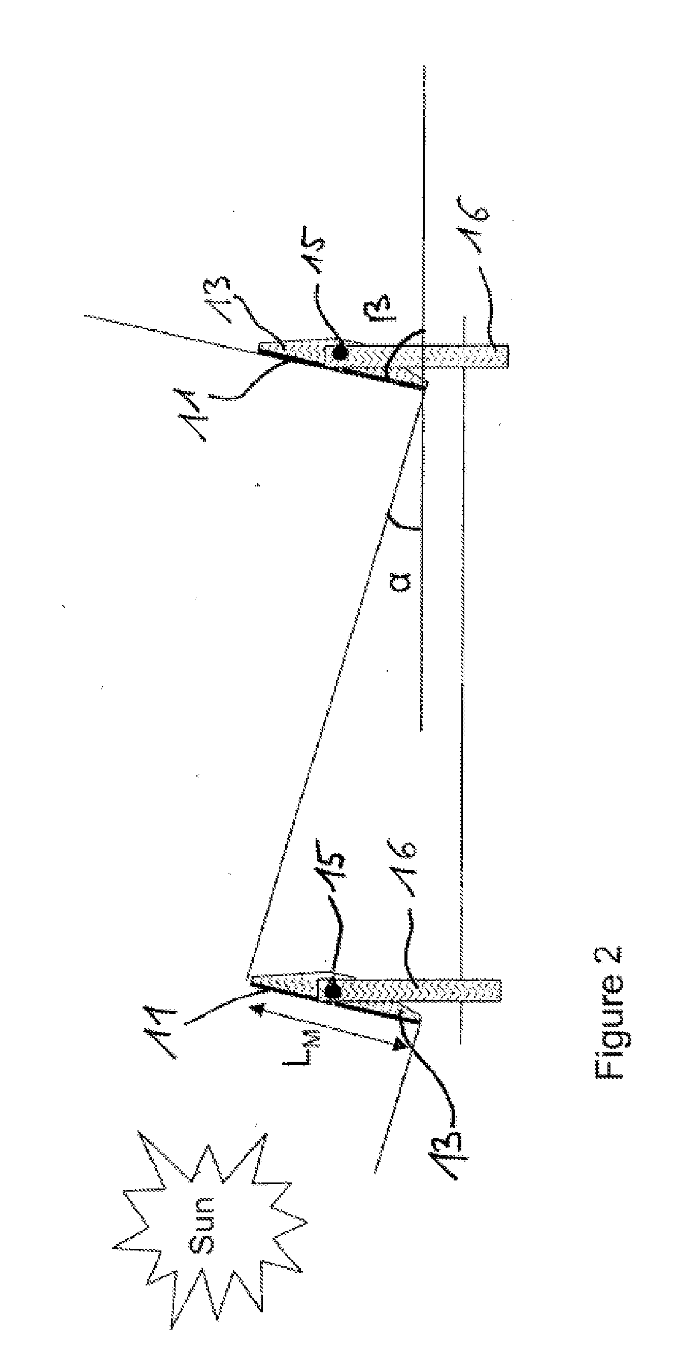
[0047]The known solar array according to FIG. 2 differs from that of FIG. 1 in that the solar modules 11 situated on poles 16 may be swiveled about an axis 15. This allows the solar modules to track the course of the solar trajectory. At low solar altitude (flat angle of incidence) the solar modules may be oriented in a relatively flat configuration, thus making it possible to avoid casting shadows on an adjacent solar ...


PUM


Abstract

A solar array in the form of a photovoltaic installation comprises a plurality of interspaced solar modules. Also provided, at a distance from the solar modules (11), are movable reflector elements (19) which have reflectors for reflecting the solar radiation and which are oriented in such a way that collected solar radiation is at least partially projected onto the receiving surface of an adjacent solar module (11).

Description

CROSS-REFERENCE TO RELATED APPLICATIONS[0001]This application claims priority to PCT / CH2008 / 000315 filed on Jul. 14, 2008, and to CH113107 filed on Jul. 13, 2007, the entirety of each of which is incorporated by this reference.BACKGROUND[0002]1. Field of the Invention[0003]The present invention relates to a solar array, in particular a photovoltaic installation, comprising a plurality of interspaced solar modules.[0004]2. Background of the Invention[0005]Three different variants are typically used for configuring conventional photovoltaic modules in solar power plants. According to a first variant, fixedly mounted solar modules with a southerly orientation are used (in the Northern Hemisphere; otherwise, a northerly orientation is used)[0006]According to a second variant, module tracking systems are used, which by means of uniaxial rotation allow tracking of the normal vector of the module panel for optimized orientation to the direction of solar radiation.[0007]According to a third...

Claims


Application Information

Patent Timeline
IPC IPC(8): H01L31/052
CPCF24J2/16F24J2/541F24J2002/0084F24J2002/0416F24J2002/1085F24J2002/5451H02S40/22F24J2002/5468H01L31/0232H01L31/042Y02E10/47Y02E10/52F24J2002/5458H02S20/32F24S2020/186F24S2023/874F24S2020/16F24S2030/133F24S30/425F24S2030/131F24S2030/136F24S23/77
Inventor BUCHEL, ARTHUR R.BAUMGARTNER, FRANZ
Owner BUCHEL ARTHUR R
Learn More