
Rotor Angle Stability Prediction Using Post Disturbance Voltage Trajectories

a technology of voltage trajectories and rotational angle, which is applied in the direction of dynamo-electric converter control, testing/monitoring control systems, instruments, etc., can solve the problems of rotor angle, frequency or voltage instability, transient instability, and limited effectiveness of local measurement based out-of-step protection systems in minimizing effects

Active Publication Date: 2011-01-27
RAJAPAKSE ATHULA
View PDF6 Cites 51 Cited by
  • Summary
  • Abstract
  • Description
  • Claims
  • Application Information

AI Technical Summary

Benefits of technology

[0008]According to one aspect of the invention there is provided a method of monitoring a rotor angle

Problems solved by technology

However, they are not designed to be immune to all possible events; unexpected events can happen in the system leading to rotor angle, frequency or voltage instability [2].
However, in large power systems it is also possible that the transient instability occurs in the later swings, mainly related to a lack of sufficient damping torque [3 ] [4].
Effectiveness of such local measurement based out-of-step protection systems is limited in minimizing the effects of system wide disturbances [1].
However, implementation of event based special protection systems can be extremely complex, cumbersome and expensive [6], [7]; this is because a large number of tele-protection systems are needed to convey all relevant system contingencies to the stations that must execute corrective actions.
Despite the limited success of these schemes, systematic approaches for designing wide area protection and control systems against the large disturbance rotor angle instability is a necessity.

Method used


Image

  • Rotor Angle Stability Prediction Using Post Disturbance Voltage Trajectories
  • Rotor Angle Stability Prediction Using Post Disturbance Voltage Trajectories
  • Rotor Angle Stability Prediction Using Post Disturbance Voltage Trajectories

Examples


example of application

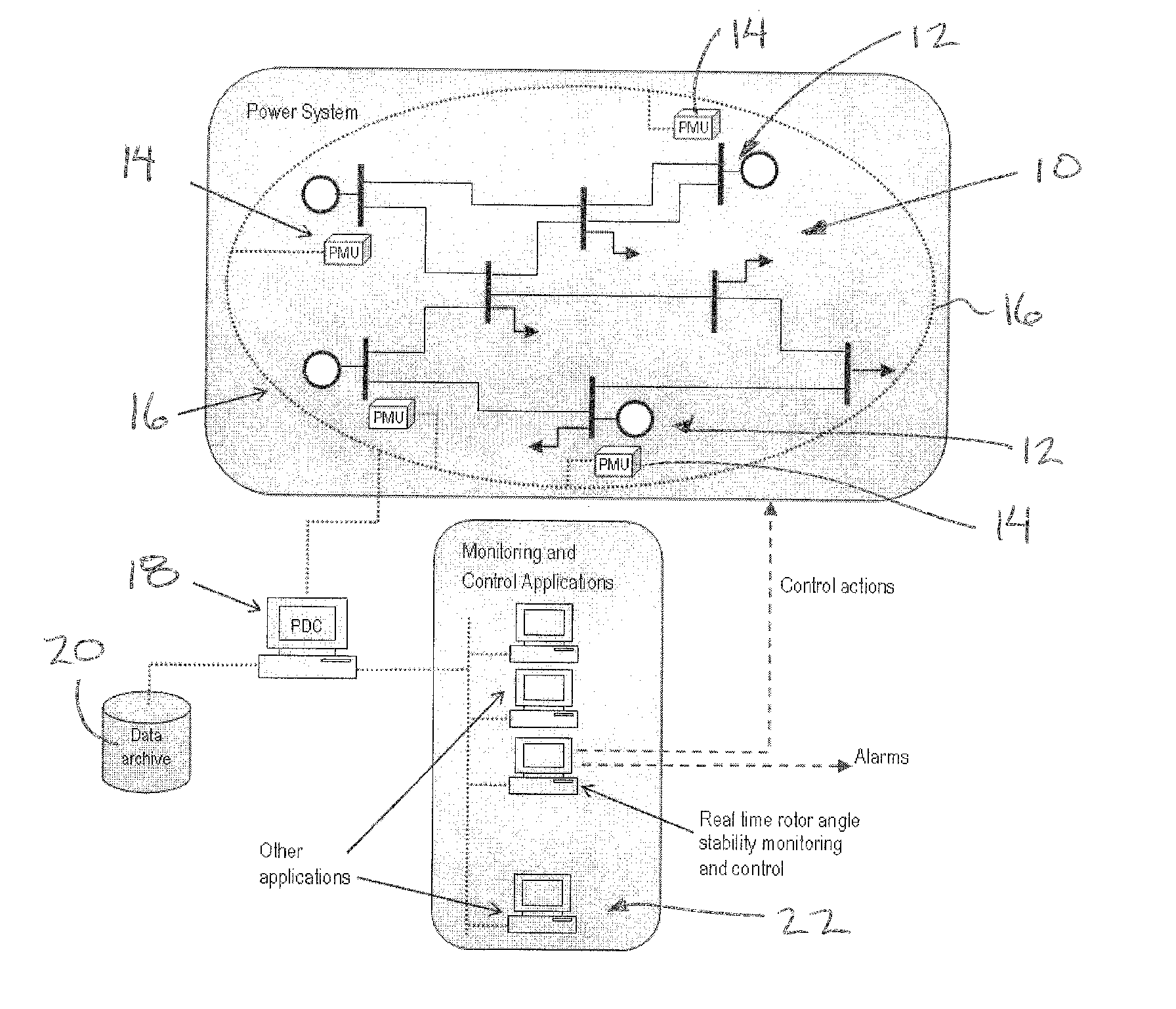
[0108]In order to demonstrate the concept, a case study is presented using IEEE 39-bus test system (New England test system) shown in FIG. 6 [18]. This system with 10 generators, (one of which is actually an equivalent generator representing a large system) is often used as a test case for rotor angle and small signal stability studies.

Database of Dynamic Simulations

[0109]A large number of contingencies were simulated using TSAT dynamic simulation program [19]. The contingencies included three-phase to ground faults on the busbars and three-phase to ground faults on transmission lines at different locations (25%, 50%, and 75% of the length). It was assumed that all faults were cleared after 5 cycles by removing the respective line or the busbar. These faults were repeated at four different load levels (base load, base load plus 5%, 7% and 10%). This gave a database of 176 simulation cases, of which 120 were stable faults and 56 were unstable faults. From this simulation database, 75...


PUM


Abstract

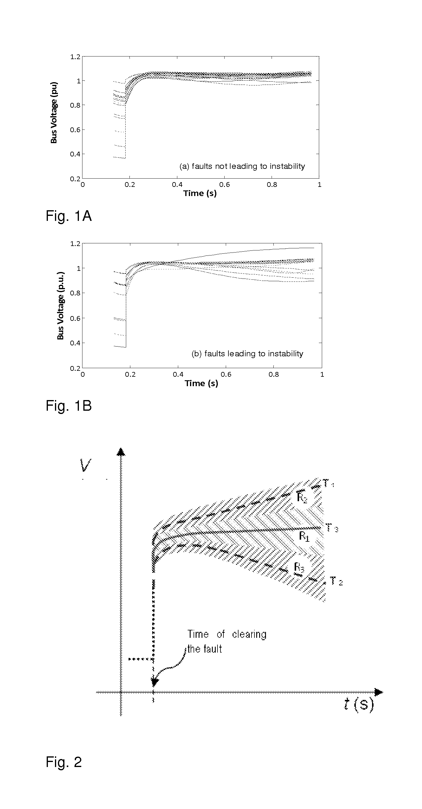
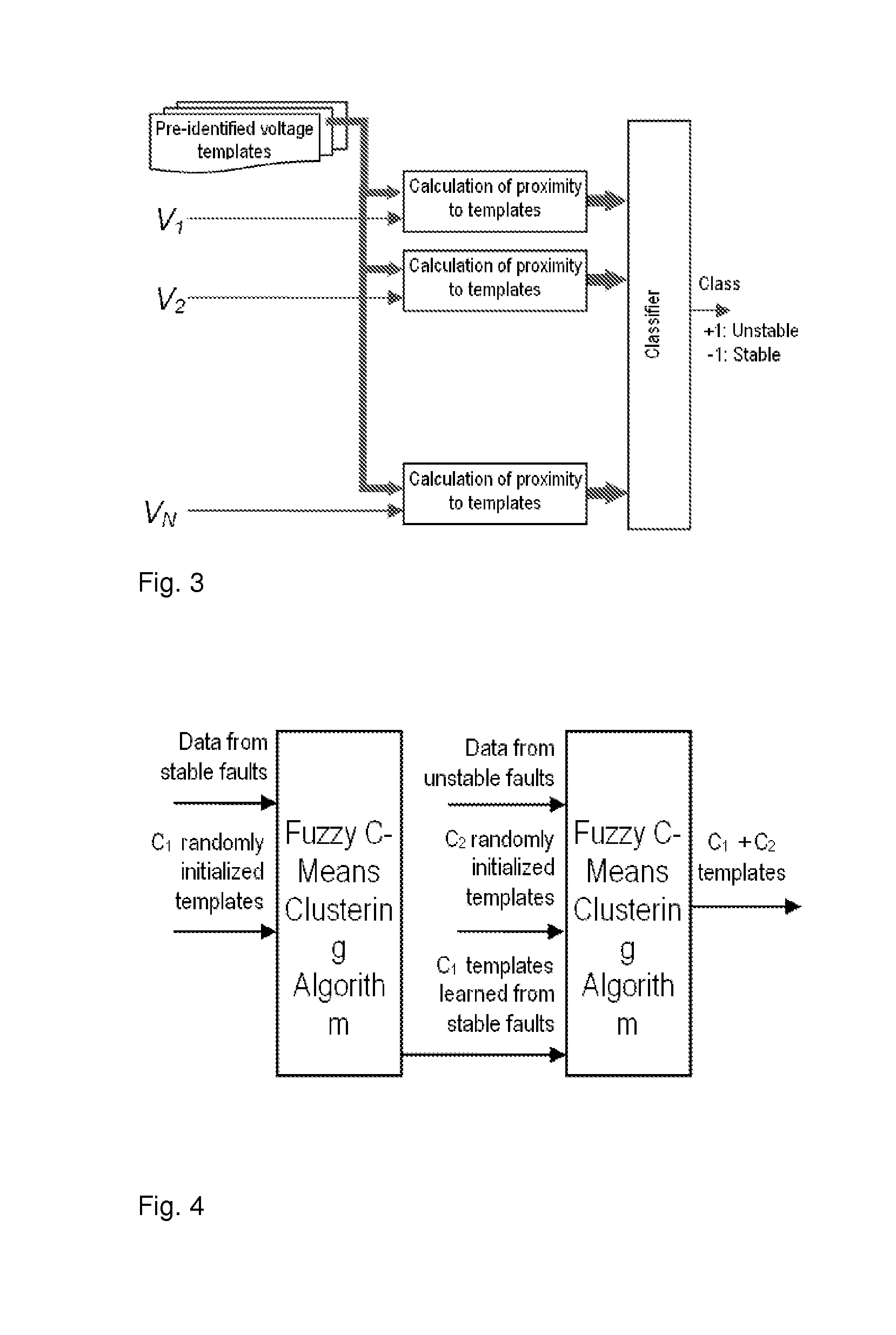
A new method for predicting the rotor angle stability status of a power system immediately after a large disturbance is presented. The proposed two stage method involves estimation of the similarity of post-fault voltage trajectories of the generator buses after the disturbance to some pre-identified templates and then prediction of the stability status using a classifier which takes the similarity values calculated at the different generator buses as inputs. The typical bus voltage variation patterns after a disturbance for both stable and unstable situations are identified from a database of simulations using fuzzy C-means clustering algorithm. The same database is used to train a support vector machine classifier which takes proximity of the actual voltage variations to the identified templates as features.

Description

[0001]This application claims the benefit under 35 U.S.C. 119(e) of U.S. provisional application Ser. No. 61 / 227,996, filed Jul. 23, 2009.FIELD OF THE INVENTION[0002]The present invention relates to a system and method for monitoring a stability condition in a power system comprising a plurality of generator buses by evaluating a trajectory of the voltage magnitude of each generator bus following a detected fault condition.BACKGROUND[0003]Power systems are designed to be able to adjust to various disturbances such as faults, large changes in loads or loss of generation and continue to operate satisfactorily within the desired bounds of voltage and frequency [1]. However, they are not designed to be immune to all possible events; unexpected events can happen in the system leading to rotor angle, frequency or voltage instability [2]. The rotor angle instability may be initiated either by a small disturbance to the system such as a change in load or a large disturbance such as a fault ...

Claims


Application Information

Patent Timeline
IPC IPC(8): G06F1/28
CPCG05B23/0254H02J3/24H02J2003/007Y02E60/76Y04S10/265Y04S40/22Y02E60/728H02J2203/20Y02E60/00Y04S10/00Y04S40/20Y04S10/22Y02E40/70H02J3/242
Inventor RAJAPASKE, ATHULA DAYANARTH
Owner RAJAPAKSE ATHULA
Learn More