
Device for controlling the operation of a radiocommunication electronic module, and corresponding electronic circuit

a radiocommunication electronic module and radiocommunication technology, applied in the field of radiocommunications, can solve the problems of low autonomy of radiocommunication devices implementing this first known technique, low power, and low power, and achieve the effect of increasing the rise and fall times of the first signal

Inactive Publication Date: 2011-01-27
SIERRA WIRELESS
View PDF12 Cites 0 Cited by
  • Summary
  • Abstract
  • Description
  • Claims
  • Application Information

AI Technical Summary

Benefits of technology

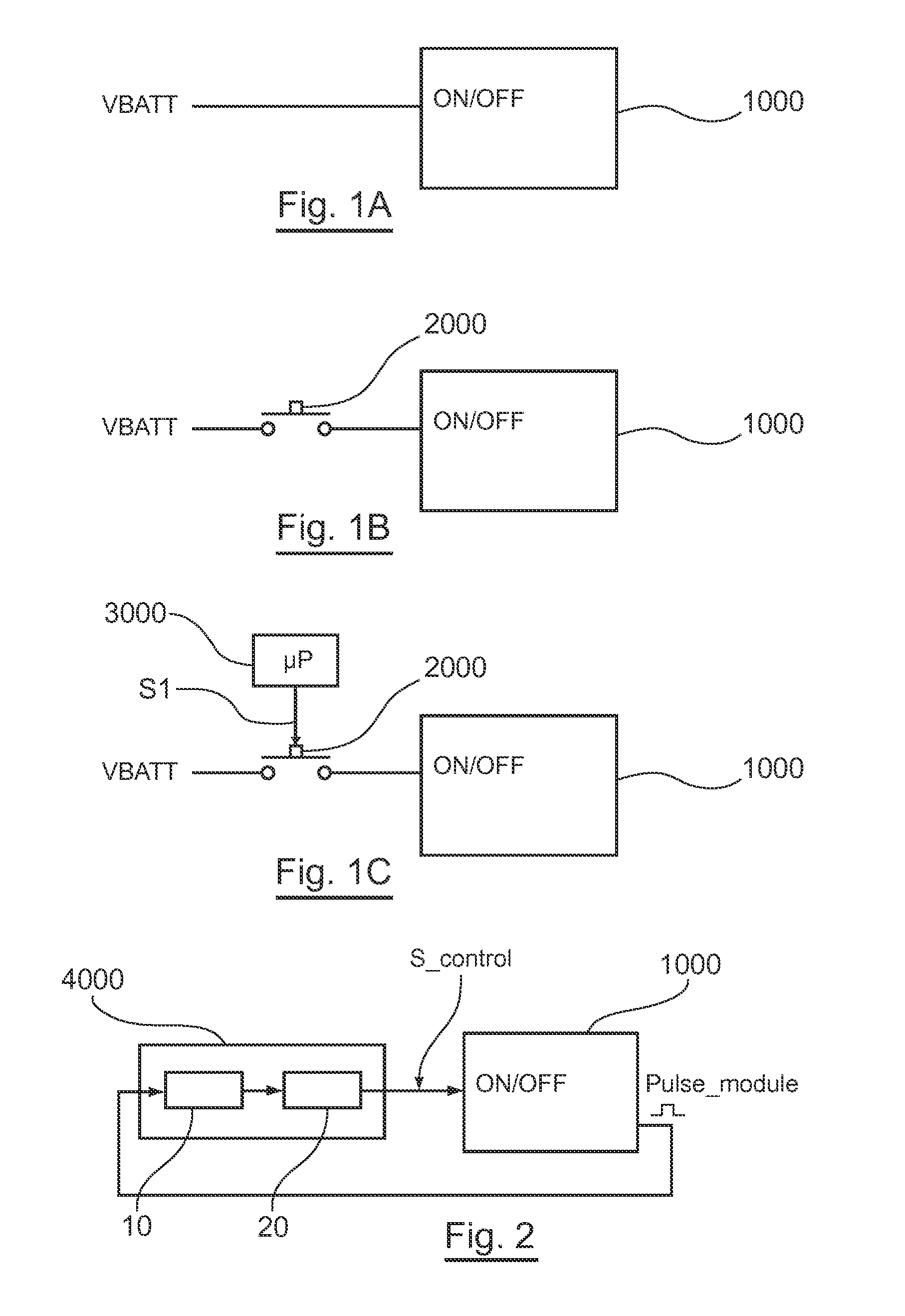
[0033]As such, an embodiment of the invention is based on an entirely new and inventive approach for the controlling of the operation of a radiocommunication module. Indeed, an embodiment of the invention proposes a self-adjusting control system. More precisely, it is proposed that a control signal according to two signals be generated, and in particular a signal coming from the module. In other terms, the logic state of the control signal depends on the logic states of the signals received by the means for controlling. The activating and the deactivating of the module are therefore controlled by the module itself. As such, it is possible to simply and effectively control the operation of a radiocommunication module, and this, contrary to the aforementioned technique of prior art, without using an external microprocessor that takes up space and that is expensive. On the contrary, an embodiment of the invention proposes to use all or a portion of the internal intelligence of the module to control the switching of the control signal.
[0034]Advantageously, said means of controlling include means for detecting a pulse, making it possible to block said means for switching as long as said means for detecting do not indicate that a pulse is received on at least one of said first and second inputs.
[0035]The means of controlling therefore make it possible to maintain the module in its current state (activated or deactivated), as long as a pulse is not detected.
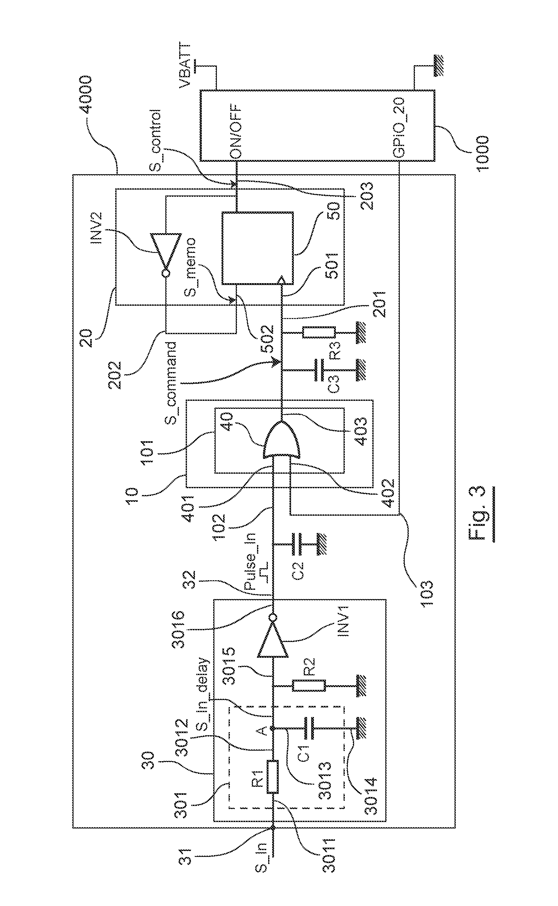
[0045]The means for slowing down make it possible to increase the rise and fall times of the first signal. For example, the means for slowing down are formed by an RC circuit.

Problems solved by technology

Solely for the purposes of illustration, the disadvantages of prior art are presented hereinafter in the case where the radiocommunication electronic module is, for example, a module of the “WISMO” (registered trademark) family implementing the “Open AT” (registered trademark) concept of the WAVECOM company (applicant of this patent application).
It is clear that these disadvantages can be transposed to any other type of radiocommunication module.
However, this remains insufficient.
Indeed, the radiocommunication devices implementing this first known technique have a low autonomy.
In other terms, this first known technique does not favour the use of batteries of small size and of low power.
Moreover, with such a technique, it is not possible to programme the real time clock, due to the fact that a low logic state is never applied on the “ON / OFF” activation input of the module.
Indeed, the ergonomics of this second known technique is limited by the fact that the user must, at the moment when the module is turned off, be physically within range of the device wherein the module is embedded.
This technique therefore does not favour the mobility of the user.
Furthermore, and in particular for the reason mentioned hereinabove, this second technique is poorly adapted for the particular case of telemetry using radiocommunication devices placed in the natural environment (ocean, desert, volcanic environment, etc.).
Although this method of automatic control represented considerable progress in the mechanism of controlling (activating / deactivating) a radiocommunication module, this method nevertheless has the disadvantage of requiring a microprocessor which takes up space and is expensive in terms of price and electric consumption.
As such, it is possible to simply and effectively control the operation of a radiocommunication module, and this, contrary to the aforementioned technique of prior art, without using an external microprocessor that takes up space and that is expensive.

Method used


Image

  • Device for controlling the operation of a radiocommunication electronic module, and corresponding electronic circuit
  • Device for controlling the operation of a radiocommunication electronic module, and corresponding electronic circuit
  • Device for controlling the operation of a radiocommunication electronic module, and corresponding electronic circuit

Examples


Embodiment Construction

[0057]As shown in FIG. 2, the general principle of an embodiment of the invention is based on the generation (by a device for controlling 4000) of a control signal S_control using a signal Pulse_module issued by a radiocommunication module 1000.

[0058]According to an embodiment of the invention, means of controlling 10 receive the signal Pulse_module coming from the module, and where applicable, detect a pulse. These means of controlling 10 make it possible, after a positive detection of a pulse, to activate means for switching 20 making it possible to switch the control signal S_control from a low logic state to a high logic state, or vice versa.

[0059]In relation with the FIG. 3, a device for controlling 4000 according to a particular embodiment of the invention shall now be described.

[0060]In this embodiment, the device for controlling 4000 comprises:[0061]means for generating 30 a first pulse Pulse_In specific to an embodiment of the invention;[0062]means for controlling 10 includ...


PUM


Abstract

A device is provided for controlling operation of a radiocommunication electronic module using a control signal. The device includes a circuit for switching the control signal between a high logic state and a low logic state or vice versa, and a circuit for controlling the switching circuit. The control circuit generates a control signal. The module includes an activation input receiving the control signal. The control circuit includes: a first input receiving a first signal representative of a supply voltage; and a second input receiving a second signal from the module.

Description

CROSS-REFERENCE TO RELATED APPLICATIONS[0001]This application is a Section 371 National Stage Application of International Application No. PCT / EP2008 / 066515, filed Dec. 1, 2008 and published as WO 2009 / 071505 on Jun. 11, 2009, not in English.STATEMENT REGARDING FEDERALLY SPONSORED RESEARCH OR DEVELOPMENT[0002]None.THE NAMES OF PARTIES TO A JOINT RESEARCH AGREEMENT[0003]None.FIELD OF THE DISCLOSURE[0004]The field of the disclosure is that of radiocommunications and more particularly of radiocommunication devices comprising a radiocommunication electronic module.[0005]More precisely, the disclosure concerns the controlling of the operation of such modules by means of a control signal.[0006]The disclosure applies in particular, but not exclusively, in the case where the radiocommunication electronic module is, for example, a module of the “WISMO” (registered trademark) family of the WAVECOM company (applicant of this patent application). The WAVECOM company has indeed for several years...

Claims


Application Information

Patent Timeline
IPC IPC(8): H04B1/00
CPCH04W52/028Y02D30/70
Inventor PAULY, FREDERICDU, CHIENG KIENG
Owner SIERRA WIRELESS
Learn More