
Two-part loading card edge connector and component assembly

a technology of edge connectors and loading cards, applied in semiconductor devices for light sources, lighting and heating apparatus, lighting support devices, etc., can solve problems such as saving considerable time and expense, and achieve the effect of convenient manufacturing and assembly

Active Publication Date: 2011-01-27
KYOCERA AVX COMPONENTS CORP
View PDF20 Cites 21 Cited by
  • Summary
  • Abstract
  • Description
  • Claims
  • Application Information

AI Technical Summary

Benefits of technology

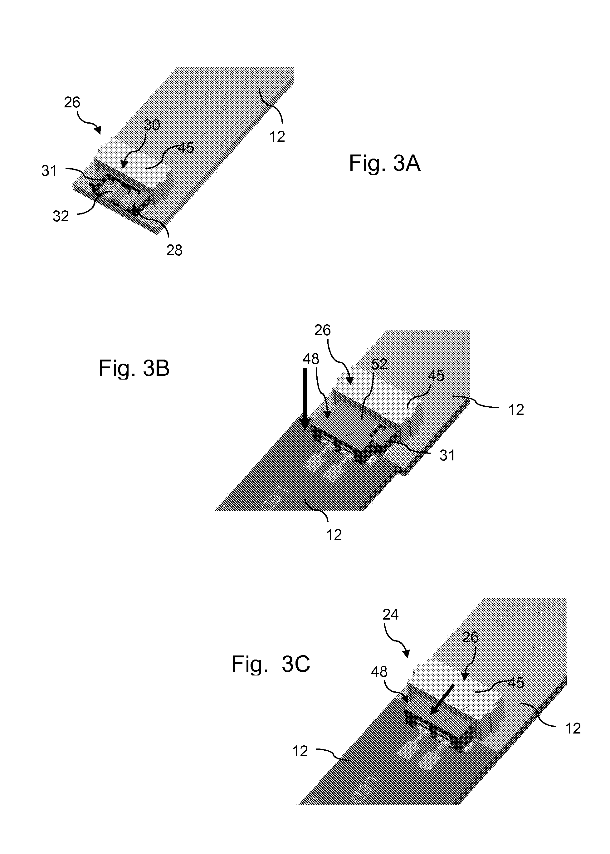
[0012]The two-component surface mount connector between the adjacent LED boards can take on various configurations in accordance with the invention. In a particularly unique embodiment, the connector includes a male component mounted at an end of a first LED board, and a female component mounted at the abutting end of a second LED board. The female component includes a socket having an open top configured for receipt of the male component in a top loading process such that electrical connection is made between the first and second LED boards without relative longitudinal movement between the LED boards. This configuration is particularly useful in that the LED boards can be inserted into and removed from a light fixture or other component simply by displacing the boards in a vertical or transverse direction relative to the longitudinal axis of the aligned group of boards. A single board can be inserted or placed into the grouping without having to disconnect the other boards or disassemble the fixture. This configuration will save considerable time and expense in the ongoing maintenance of LED light fixtures or components utilizing a plurality of LED boards.
[0014]The male component of the electrical connector includes an insulative base body with at least two electrical contacts that have a first section at a bottom surface of the insulative base body spaced apart a distance corresponding to a connector pad footprint on an end of an adjacent LED board. The male component further includes an insulative plug member that extends transversely from the base body beyond the end of the LED board. The electrical contacts in the male component have a second section that extends at least partially onto the plug member. With this unique configuration of the female and male components, mating electrical contact is made between the components by inserting the plug member of the male component into the open top socket of the female component from above in a top loading process such that the electrical contacts on the plug member engage against the electrical contacts in the open top socket. The top loading process does not require relative longitudinal movement between the LED boards to engage the connector components.
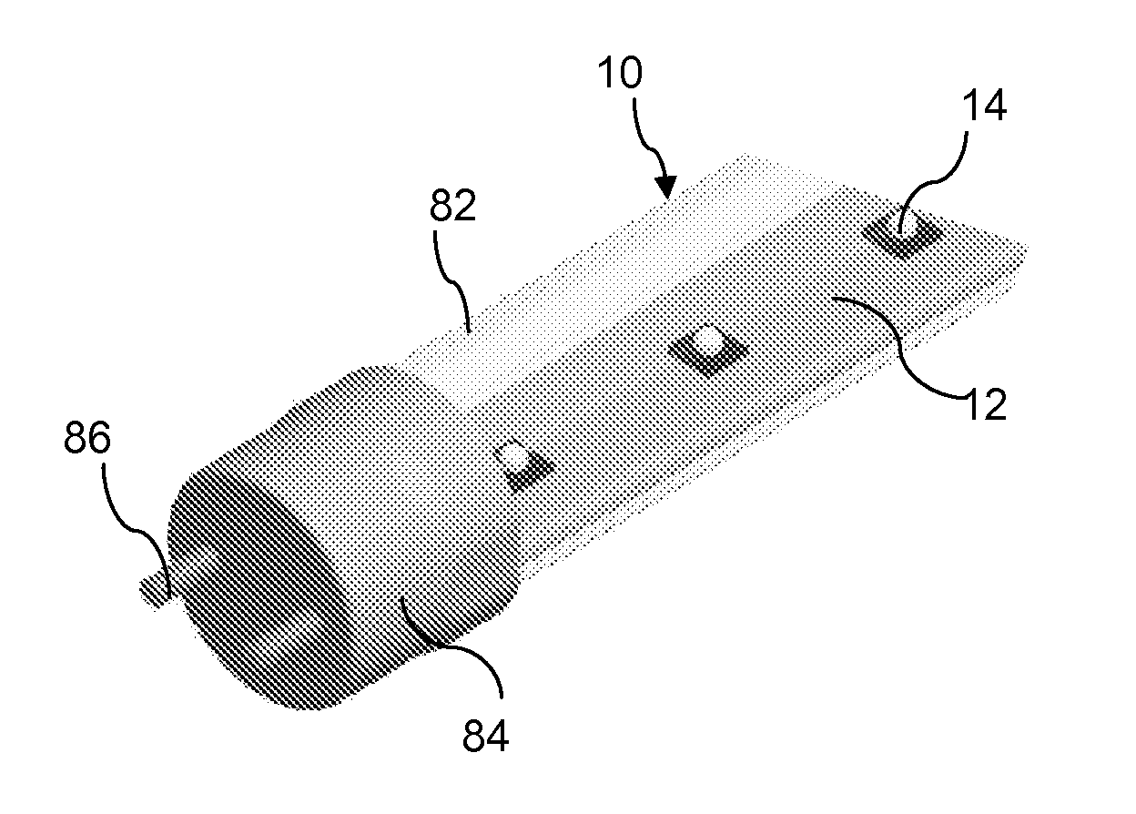
[0018]The present invention also encompasses an LED light tube assembly that is configured for receipt in a lighting fixture. This light tube assembly includes a light tube having an end cap connector at each opposite longitudinal end thereof. In this manner, the LED light tube assembly may resemble a conventional fluorescent light tube. A plurality of LED boards are connected in an end-to-end abutting configuration within the light tube, with each of the LED boards having at least one LED bulb and electrical connector pads configured at each opposite end of the board. The electrical connector pads on the extreme opposite ends of the connected boards are in electrical mating contact with the end cap connectors. As described above, a two-component surface mount electrical connector connects the connector pads of aligned ends of adjacent LED boards within the light tube such that one end of a first LED board is in electrical contact to an end of a second LED board. In this manner, any desired number of LED boards can be connected in an end-to-end direct abutting manner within the light tube. Thus, various sizes and power ratings of the light tube can be easily manufactured and assembled using a standard, single size LED board, end cap connectors, and board connectors. Only the length of the light tube would vary to accommodate the desired number of LED boards.
[0019]The LED light tube assembly is particularly unique in that it can be readily configured for receipt in an existing fluorescent light fixture. The end cap connectors would include pin contacts configured for receipt in receptacles in the fluorescent light fixture. Thus, the LED light tube can be a replacement bulb for existing fluorescent light fixtures.

Problems solved by technology

This configuration will save considerable time and expense in the ongoing maintenance of LED light fixtures or components utilizing a plurality of LED boards.

Method used


Image

  • Two-part loading card edge connector and component assembly
  • Two-part loading card edge connector and component assembly
  • Two-part loading card edge connector and component assembly

Examples


Embodiment Construction

[0039]Reference will now be made in detail embodiments of the invention, examples of which are illustrated in the drawings. The various embodiments are presented herein for sake of explaining aspects of the invention, and should not be interpreted as a limitation of the invention. For example, features illustrated or described with respect to one embodiment can be used with another embodiment to yield still a further embodiment. It is intended that the present invention include these and other modifications and variations as come within the scope and spirit of the invention.

[0040]FIGS. 1 and 2 illustrate a unique embodiment incorporating aspects of the invention. An LED light assembly 10 is illustrated in FIG. 1. This assembly 10 includes a plurality of individual LED printed circuit boards (PCB) 12. Each of these boards 12 includes at least one LED bulb 14. In the illustrated embodiment, each board 12 includes four bulbs 14. The boards 12 may be manufactured so as to have a standar...


PUM


Abstract

An LED light assembly includes a plurality of LED printed circuit boards (PCB), with each LED PCB having at least one LED bulb and electrical connector pads configured at each opposite end of the boards. A top loading two-component surface mount electrical connector is configured to connect one end of a first LED PCB to an end of a second said LED PCB such that the first and second LED PCBs are electrically connected in an abutting end-to-end configuration. The connected LED PCBs may be configured in a light tube that includes connector end caps for mounting the light tube in a light fixture.

Description

PRIORITY CLAIM[0001]The present application claims priority to U.S. Provisional Application Ser. No. 61 / 228,795, filed Jul. 27, 2009.BACKGROUND[0002]The use of LED (Light Emitting Diode) lights is becoming increasingly popular in a wide variety of lighting applications. Significant advances have been made in LED lighting technology, which have made the use of LED lights more affordable and desirable in various industrial, household, and other environments requiring expanded lighting systems.[0003]LED lights offer significant advantages over traditional incandescent lighting systems. With incandescent bulbs, the expense is not only the cost of replacement bulbs, but the labor and costs associated with frequent replacement of the bulbs. This expense can be significant where there are a large number of installed bulbs. For example, the maintenance costs to replace bulbs in large office buildings, public transportation vehicles and systems, and the like, can be quite high. These issues ...

Claims


Application Information

Patent Timeline
Patent Type & Authority Applications(United States)
IPC IPC(8): F21S4/00H01R12/14
CPCF21K9/17F21Y2101/02F21Y2103/003F21V23/06H05K2201/10106H05K2201/10189H05K1/142F21K9/27F21Y2103/10F21Y2115/10H01R12/712H05K1/14F21S4/28F21V19/001F21V19/003F21V19/008F21V21/005H01L25/0753
Inventor BISHOP, PETERHUNTLEY, NORMAN
Owner KYOCERA AVX COMPONENTS CORP
Learn More