
Method and circuit for controlling radiant heat of transistor using metal-insulator transition device

a technology of transition device and transistor, which is applied in the direction of pulse generator, pulse technique, instruments, etc., can solve the problems of generating a large amount of heat, requiring a certain amount of time to replace the fuse, and consuming a certain amount of time, so as to overcome the time to replace or the cost of replacemen

Inactive Publication Date: 2011-01-27
ELECTRONICS & TELECOMM RES INST
View PDF3 Cites 15 Cited by
  • Summary
  • Abstract
  • Description
  • Claims
  • Application Information

AI Technical Summary

Benefits of technology

[0023]According to the present invention, in the method and circuit for controlling heat generation of a transistor, an MIT device attached to a power transistor prevents the power transistor from wrongly operating due to an excessive increase in its temperature. Thus, all devices or system to which the power transistor supplies power can be protected.
[0024]Accordingly, the circuit for controlling heat generation of a power transistor can be used in all electric-electronic circuit system using a power transistor, such as a cellular phone, a notebook computer, a cell charging circuit, a motor controlling circuit, a power controlling circuit and power supply of a electric-electronic device, a power amplifier including audio equipment, and an inner circuit of a integrated functional integrated circuit (IC).
[0025]In addition, since the MIT device can be semi-permanently used without requiring the MIT device to be changed or replaced, the problem with time to replace or costs incurred due to replacement can be overcome.

Problems solved by technology

Since power transistors supply power, they generate a large amount of heat.
However, a problem occurs when changing / replacing the fuse.
When changing / replacing the fuse, although the fuse is inexpensive, it take a certain amount of time and costs are incurred when hanging / replacing the fuse, and economic loss may be caused since equipment cannot be used during changing / replacing the fuse.
In this regard, since the size of a heat sink is greater than that of a transistor, the heat sink occupies a large space in a power system, which is an obstacle to miniaturization of such power systems.

Method used


Image

  • Method and circuit for controlling radiant heat of transistor using metal-insulator transition device
  • Method and circuit for controlling radiant heat of transistor using metal-insulator transition device
  • Method and circuit for controlling radiant heat of transistor using metal-insulator transition device

Examples


Embodiment Construction

Industrial Applicability

[0102]The present invention relates to a metal-insulator transition (MIT) device, and more particularly, to a method and circuit for controlling heat generation of a power transistor using an MIT device. According to the present invention, in the method and circuit for controlling heat generation of a transistor, an MIT device attached to a power transistor prevents the power transistor from wrongly operating due to an excessive increase in its temperature. Thus, all devices or system to which the power transistor supplies power can be protected.

Sequence List Text

[0103]


PUM


Abstract

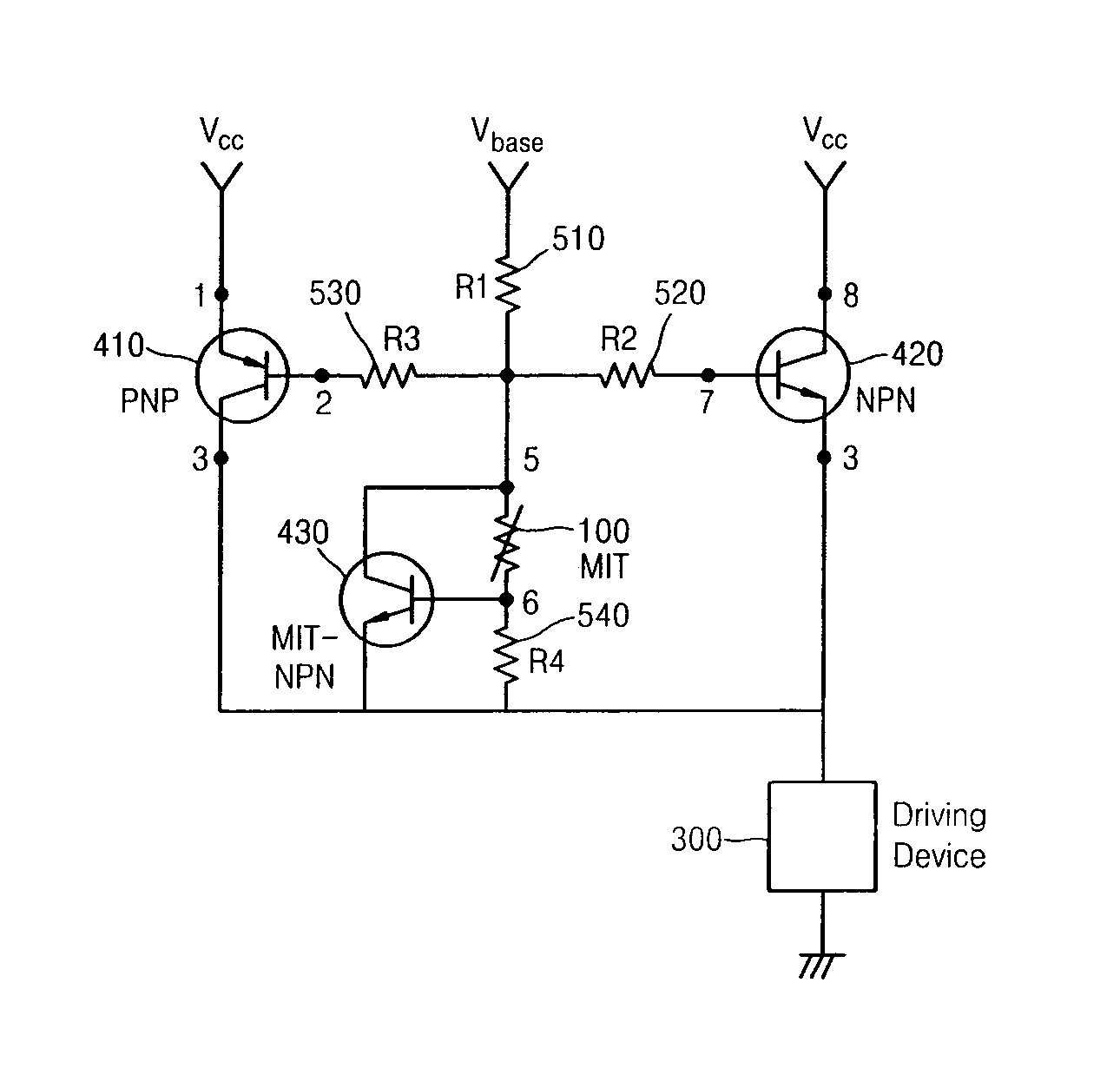
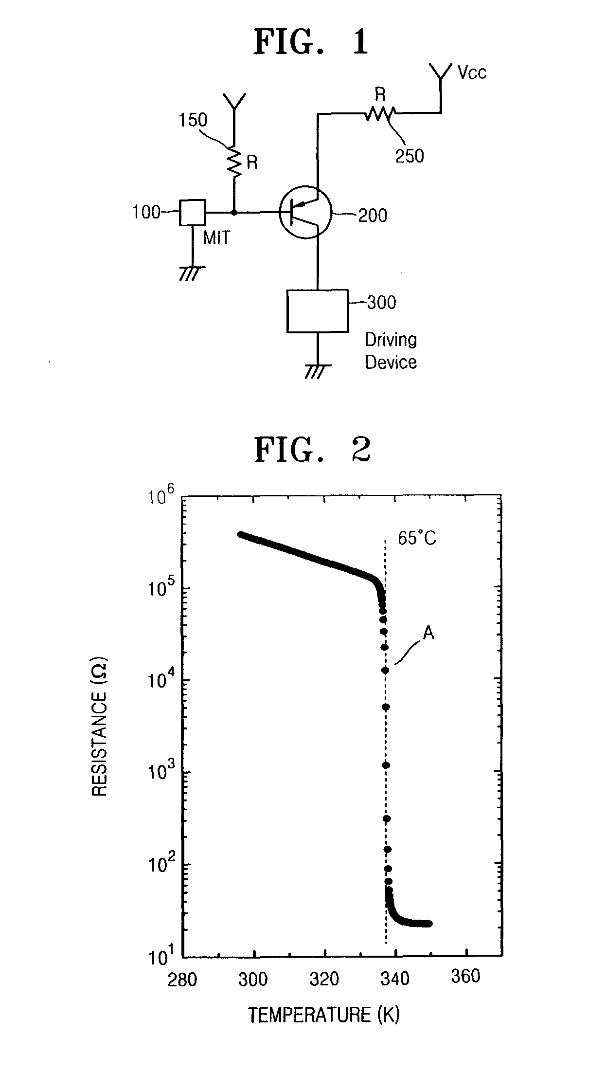
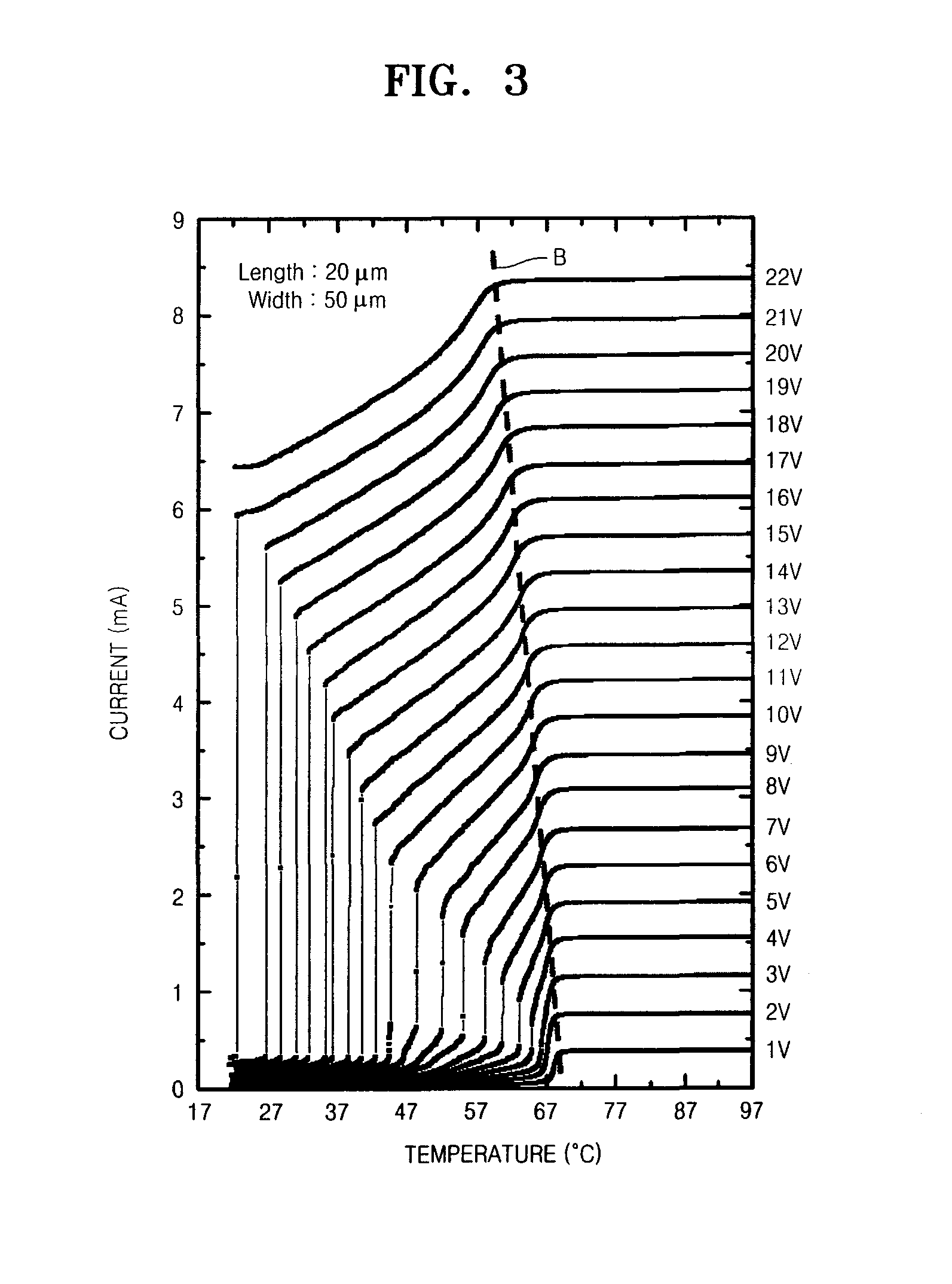
Provided are a method and circuit for controlling heat generation of a power transistor, in which the power transistor can be protected by preventing heat generation of the power transistor by using a metal-insulator transition (MIT) device that can function as a fuse and can be semi-permanently used. The circuit for controlling heat generation of a transistor includes a metal-insulator transition (MIT) device in which abrupt MIT occurs at a predetermined critical temperature; and a power transistor connected to a driving device and controlling power-supply to the driving device, wherein the MIT device is attached to a surface or heating portion of the transistor and is connected to a base terminal or gate terminal of the transistor or a surrounding circuit from a circuit point of view, and wherein when a temperature of the transistor increases to a temperature equal to or greater than the predetermined critical temperature, the MIT device reduces or shuts off a current of the transistor so as to prevent heat generation of the transistor.

Description

TECHNICAL FIELD[0001]The present invention relates to a metal-insulator transition (MIT) device, and more particularly, to a method and circuit for controlling heat generation of a power transistor using an MIT device.BACKGROUND ART[0002]Power transistors for controlling power have been widely used in industrial devices including computers. Since power transistors supply power, they generate a large amount of heat. Generally, a fuse is connected to a base or gate of a power transistor in order to protect the power transistor.[0003]The fuse breaks when the temperature thereof reaches a predetermined dangerous temperature, thereby turning-off and cooling the transistor so as to protect it. An inexpensive fuse is used in expensive equipment so that a system including the equipment can be protected by checking whether the fuse is cut. However, a problem occurs when changing / replacing the fuse.[0004]When changing / replacing the fuse, although the fuse is inexpensive, it take a certain amo...

Claims


Application Information

Patent Timeline
IPC IPC(8): H03K17/60
CPCH01L23/62H01L25/16H01L2924/0002H01L2924/00H02H3/085H02H5/047G05F3/24
Inventor KIM, HYUN TAKLEE, YONG-WOOKKIM, BONG-JUNYUN, SUN-JIN
Owner ELECTRONICS & TELECOMM RES INST
Learn More