Solar Concentrator Configuration With Improved Manufacturability And Efficiency

a solar concentrator and configuration technology, applied in the field of solar concentrators, can solve the problems of high manufacturing and installation costs, low passive solar radiation intensity, and inability to directly use most applications, and achieve the effect of reducing the weight, complexity and cost of the final solar concentrator structur

Active Publication Date: 2011-01-27
CEWA TECH
View PDF24 Cites 16 Cited by
  • Summary
  • Abstract
  • Description
  • Claims
  • Application Information

AI Technical Summary

Benefits of technology

[0014]In a preferred embodiment of the present invention, each reflector is formed of a plurality of curved petals that are disposed in a contiguous, keystone arrangement that requires minimal fixturing (e.g., epoxy) to hold the petals in place. Such an arrangement reduces the weight, complexity and cost of the final solar concentrator structure.

Problems solved by technology

However, passive solar radiation intensity is generally too low to be directly useful for most applications that require heat at high temperatures and pressures (such as running HVAC, industrial process heat, turbines, etc.).
However, the shadowing effects, large land requirements, and other considerations are some of the disadvantages of the power tower types of concentrator technologies.
One problem with these and other types of conventional concentrating solar collectors is that they are expensive to fabricate and install.
Each implementation also has requirements for specific dimensions (in terms of their surface area, lengths, etc.), offering little flexibility to adapt to application-specific situation.
Moreover, the solar collector optics are generally comprised of glass reflectors that must be painstakingly constructed and polished, require costly supporting structures, and thereafter require extensive and tedious installation.

Method used


Image

  • Solar Concentrator Configuration With Improved Manufacturability And Efficiency
  • Solar Concentrator Configuration With Improved Manufacturability And Efficiency
  • Solar Concentrator Configuration With Improved Manufacturability And Efficiency

Examples


Embodiment Construction

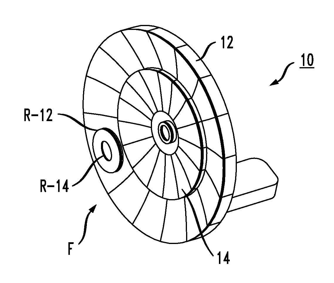
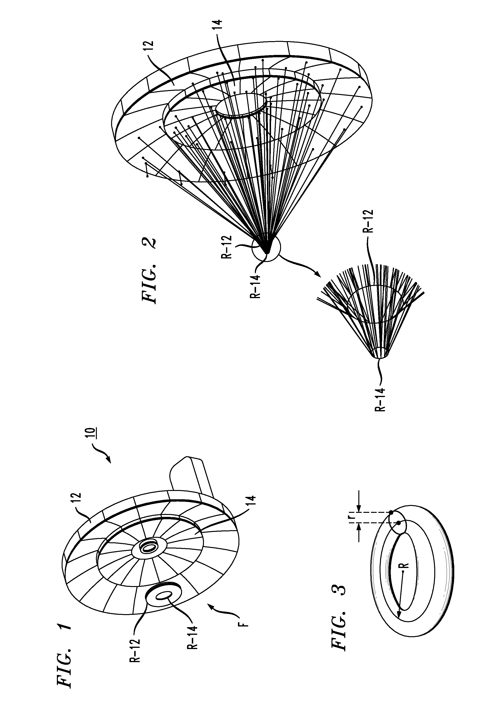
[0031]FIG. 1 is an isometric view of an exemplary solar concentrator 10 formed in accordance with the present invention. Unlike prior art solar concentrator arrangements based on creating “point” or “line” concentration of the solar radiation, the spindle toroid geometry of the inventive concentrator functions to direct the reflected solar into ring-like regions at the focal area F of concentrator 10. As mentioned above, the ring-like focal area provides a greater concentration of energy than the “line” focus associated with the prior art trough collectors, without requiring the expensive alignments associated with the prior art “point” focus associated with the prior art dish collectors.

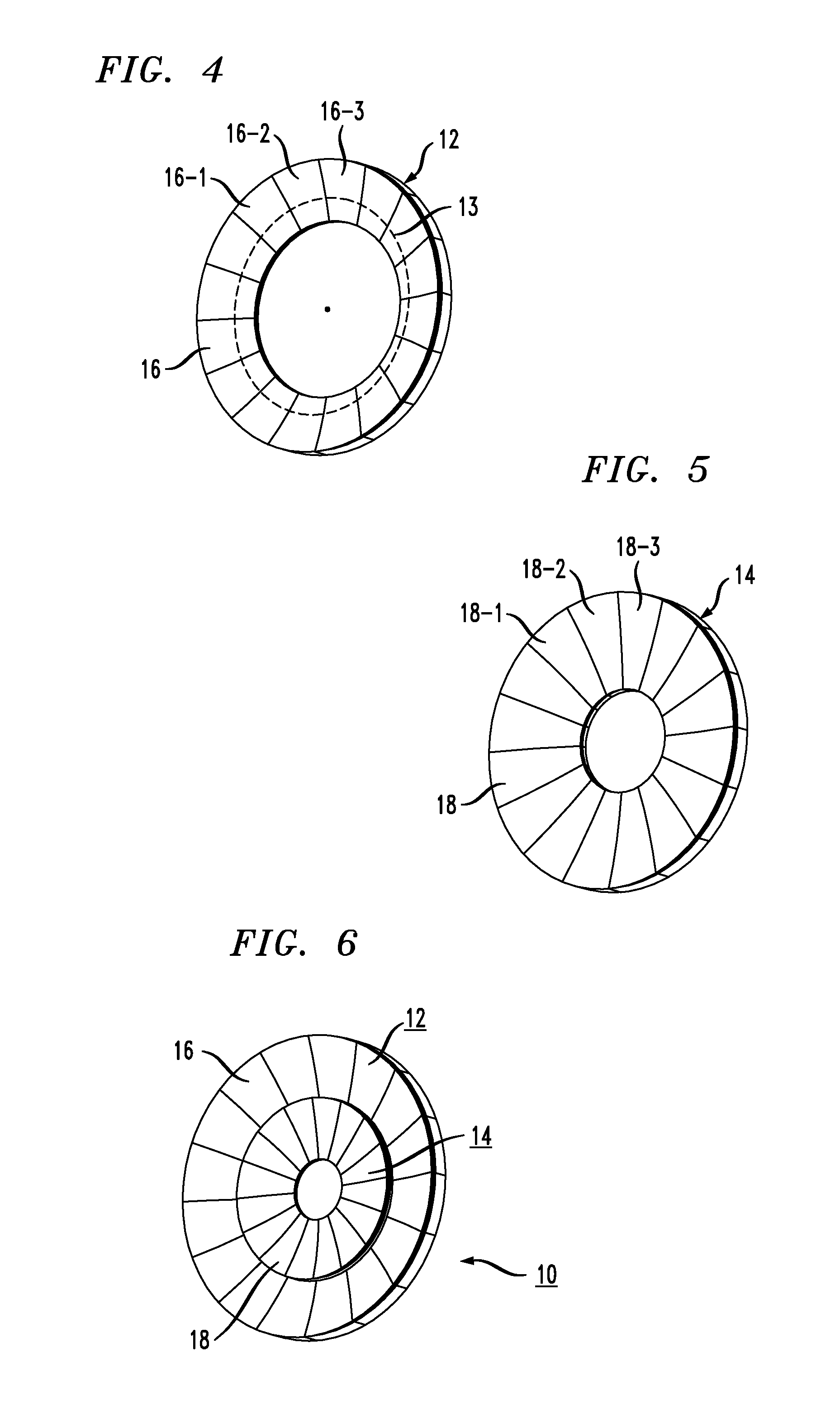
[0032]In particular, solar concentrator 10 is shown as comprising a pair of concentric reflectors including an outer reflector 12 and an inner reflector 14, where each reflector is formed of the spindle toroid geometry. As mentioned above, the use of a pair of reflectors is considered to be exemplar...


PUM


Abstract

A solar concentrator comprises a pair of concentric reflectors having a spindle toroid geometry for focusing the collected solar radiation into a ring-shaped focal area, as opposed to the “point” or “line” focus of prior art configurations. In a preferred embodiment, each reflector is formed of a plurality of curved petals that are disposed in a contiguous, keystone arrangement that requires no additional fixturing to hold the petals in place. Such an arrangement reduces the weight, complexity and cost of the final solar concentrator structure.

Description

CROSS-REFERENCE TO RELATED APPLICATION[0001]This application claims the benefit of U.S. Provisional Application No. 61 / 228,440, filed Jul. 24, 2009, which is herein incorporated by reference.TECHNICAL FIELD[0002]The present invention relates to a solar concentrator particularly well-suited for low cost applications, with easy assembly and repair and, more particularly, to a solar concentrator comprising a pair of concentric reflectors having a spindle toroid geometry for focusing the collected solar radiation into a ring-shaped focal area, as opposed to the “point” or “line” focus of prior art configurations.BACKGROUND OF THE INVENTION[0003]The incident solar radiation at the surface of the earth has fairly low intensity, somewhat variable depending on the time of the day, season and location of the earth; roughly 800-1000 watts of thermal energy per square meter of area. For the solar industry to become commercially competitive in diverse global markets as compared to the costs of ...

Claims


Application Information

Patent Timeline
Patent Type & Authority Applications(United States)
IPC IPC(8): H01L31/052F24J2/10F24S23/70F24S23/71F24S23/79F24S50/20
CPCF24J2/1047H01L31/0547F24J2/12F24J2/18F24J2002/1085F24J2002/385Y02B10/20Y02E10/42Y02E10/52F24J2/38Y02E10/47H01L31/058H02S40/00H01L31/056H01L31/052H02S40/44F24J2/1057F24S23/71F24S23/79F24S23/80F24S23/82F24S50/20F24S2023/874F24S2050/25Y02E10/60G01D5/3473H01L31/02024H02S20/32Y02E10/40
Inventor FANGMAN, JOHN STEWARTFANGMAN, MICHAEL E.FANGMAN, JOHN MATTHEWNETI, SUDHAKARSHAH-YUKICH, ARATI
Owner CEWA TECH
Why Eureka
Try Eureka