Method and arrangement in a pneumatic material conveying system

a conveying system and material technology, applied in the direction of conveyors, solid waste disposal, refuse gathering, etc., can solve the problems of preventing access, blocking the makeup air conduit, and the outlet aperture is blocked, so as to improve the efficiency of material affect, and fast and efficient draining of the supply tank

Inactive Publication Date: 2011-01-20
MARICAP OY
View PDF8 Cites 15 Cited by
  • Summary
  • Abstract
  • Description
  • Claims
  • Application Information

AI Technical Summary

Benefits of technology

[0011]The arrangement according to the invention has several remarkable advantages. By means of the invention, there is obtained a fast and efficient draining of the supply tank to the conveyor pipe. By means of the method and arrangement according to the invention, makeup air can be advantageously conducted in the vicinity of the outlet aperture so that it affects the material, such as waste material, as efficiently as possible. At the same time, however, it is possible to avoid the blocking of the outlet aperture of the supply tank, so that the operation of the material conveying system remains good. By bringing makeup air to the vicinity of the outlet aperture of the supply tank and by conducting the material by means of a partition wall element towards the outlet aperture, so that the makeup air affects the material to be discharged in the vicinity of the outlet aperture, at least during the draining step, there is achieved an extremely secure draining of the tank. By bringing makeup air to the bottom part of the material space, in the section left between the bottom part of the partition wall and the drain valve, it is possible to efficiently affect the material to be conveyed in the vicinity of the outlet aperture. By guiding the material by a partition wall that is a wall narrowing towards the outlet aperture, there is achieved an efficient, simple and functional structure for realizing the method. By bringing makeup air particularly to the section left between the bottom part of the partition wall element and the outlet aperture, there is achieved an efficient effect to the material to be conveyed. By bringing makeup air through a path that at least partly surrounds the partition wall, at least the bottom part thereof, there is achieved an efficient manipulative effect of the makeup air flow to the material to be conveyed on all sides thereof. In addition, in the method the access of makeup air to the vicinity of the outlet aperture can be adjusted, which means that for example the effect on the material can be modified. According to the invention, there can be used material supply tanks that are waste feed points, such as garbage bins or refuse chutes. The method and arrangement according to the invention are particularly well suited to be used in connection with conveyor systems of waste material, such as waste material arranged in bags.

Problems solved by technology

When the connection from the supply tank to the conveyor pipe is opened, the material packed in the vicinity of the outlet aperture may block the outlet aperture, or prevent the access of makeup air from the supply tank to the conveyor pipe.
The drawback with the arrangement of said publication is that the material may yet block the makeup air conduit, in which case it does not function in a satisfactory way.

Method used


Image

  • Method and arrangement in a pneumatic material conveying system
  • Method and arrangement in a pneumatic material conveying system
  • Method and arrangement in a pneumatic material conveying system

Examples


Embodiment Construction

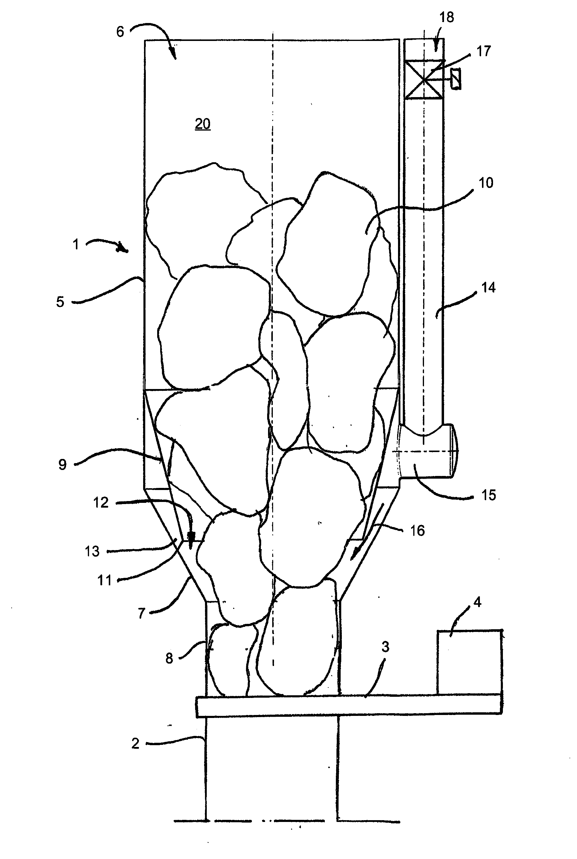
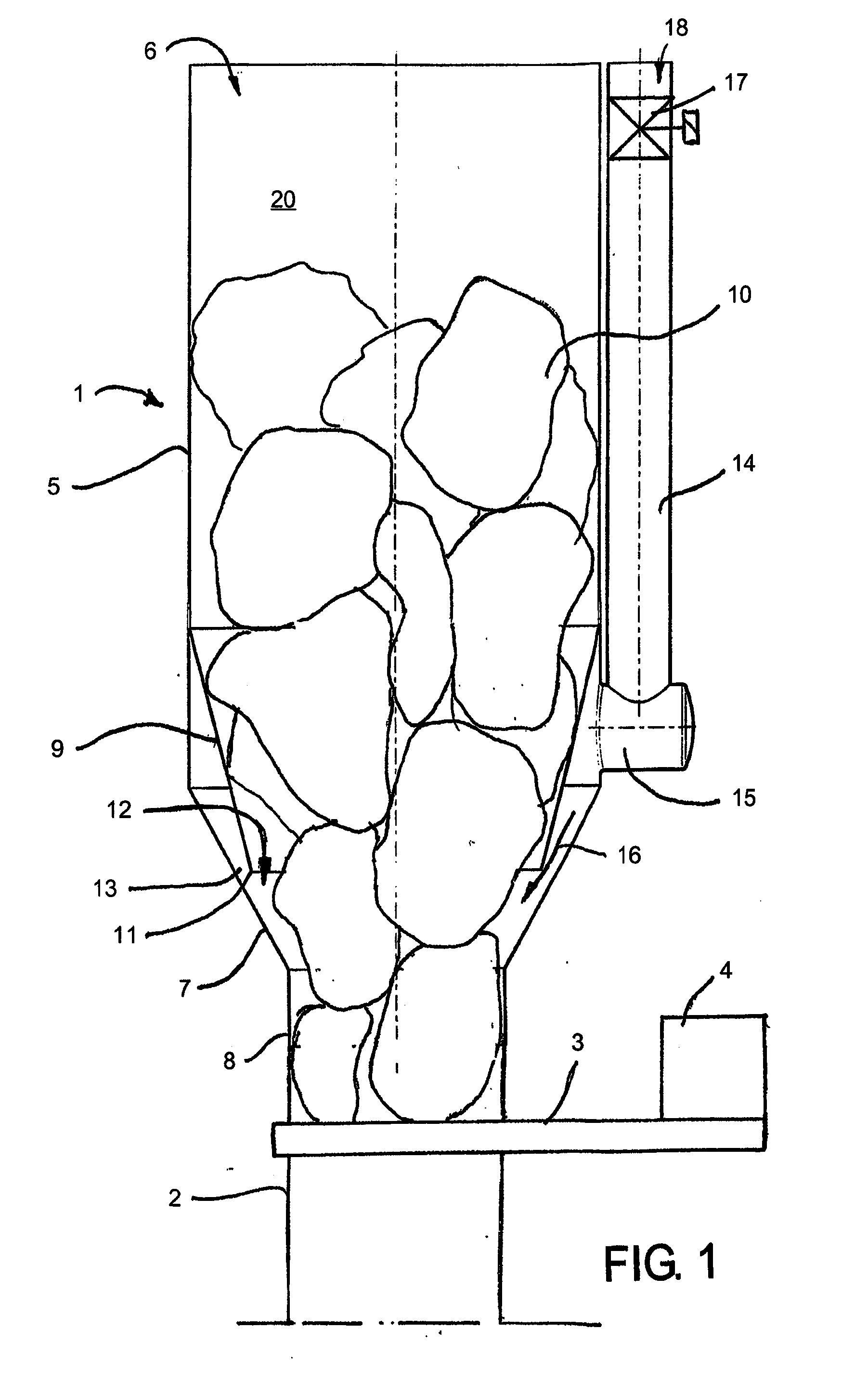
[0016]FIG. 1 is a simplified illustration of the supply tank 1 of a feed point in a material conveying system according to the invention, viewed in cross-section. The supply tank 1 is connected to a conveyor pipe 2. In between the conveyor pipe and the supply tank, there is arranged a drain valve 3, which is used as an actuator 4. In the embodiment of FIG. 1, the supply tank comprises a material space 20, defined by walls provided by a feed aperture 6 at the top end and an outlet aperture 8 at the bottom end. The material space comprises a cylindrical section 5, provided with a feed aperture 6 at the top part thereof. In between the cylindrical section 5 and the outlet aperture 8, there is arranged a narrowing section 7, which in the embodiment of the drawing has the shape of a truncated cone. After the narrowing section 7, the embodiment of the drawing includes a second cylindrical section, in connection with which there is provided the outlet aperture 8 of the supply tank. In betw...


PUM


Abstract

A method for draining the tank space (20) of a supply tank (1) in a pneumatic material conveying system, such as a waste conveying system, from material (10), such as waste material, said conveying system comprising at least one feed point of material, particularly waste material, such as a supply tank (1); said tank comprising a tank space (20); in which method the tank space is drained to a conveyor pipe (2, 100) by opening a drain valve (3), so that the underpressure prevailing in the conveyor pipe, together with the ambient pressure prevailing in the supply tank, conveys material from the supply tank to the conveyor pipe (2, 100). In the method, makeup air is brought to the vicinity of the outlet aperture (8) of the supply tank (1), and the material (10) is guided by a partition wall element (9) towards the outlet aperture, so that the makeup air affects the material to be discharged (10) in the vicinity of the outlet aperture (8), at least during the draining step. The invention also relates to an arrangement.

Description

BACKGROUND OF INVENTION[0001]The invention relates to a method according to the preamble of claim 1.[0002]The invention also relates to an arrangement according to claim 10.[0003]The invention relates generally to pneumatic material conveying systems, such as vacuum conveying systems, particularly to collecting and conveying waste, for instance household waste.[0004]There are known systems where waste is conveyed in a piping by means of suction. In these, waste is conveyed by suction for long distances in the piping. Typical for them is that a vacuum apparatus is used for achieving a pressure difference, in which apparatus underpressure in the conveyor pipe is provided with vacuum generators, such as vacuum pumps or ejector equipment. In the conveyor pipe, there is typically arranged at least one valve element, and by opening and closing said valve element, make-up air coming in the conveyor pipe is regulated. In the systems, at the material supply end, there are used supply tanks, ...

Claims


Application Information

Patent Timeline
IPC IPC(8): B65F5/00B65G53/00
CPCB65G53/50B65F5/005B65F5/00B65G53/34B09B5/00B65G53/24
Inventor SUNDHOLM, GORAN
Owner MARICAP OY
Why Eureka
Try Eureka