
Adaptive dimmer detection and control for LED lamp

a technology of led applied in the direction of electric variable regulation, process and machine control, instruments, etc., can solve the problems of mercury contamination, conventional led lamps cannot be direct replacements of incandescent lamps and dimmable fluorescent systems, and lamps represent lower environmental impa

Active Publication Date: 2011-01-20
DIALOG SEMICONDUCTOR INC
View PDF36 Cites 189 Cited by
  • Summary
  • Abstract
  • Description
  • Claims
  • Application Information

AI Technical Summary

Benefits of technology

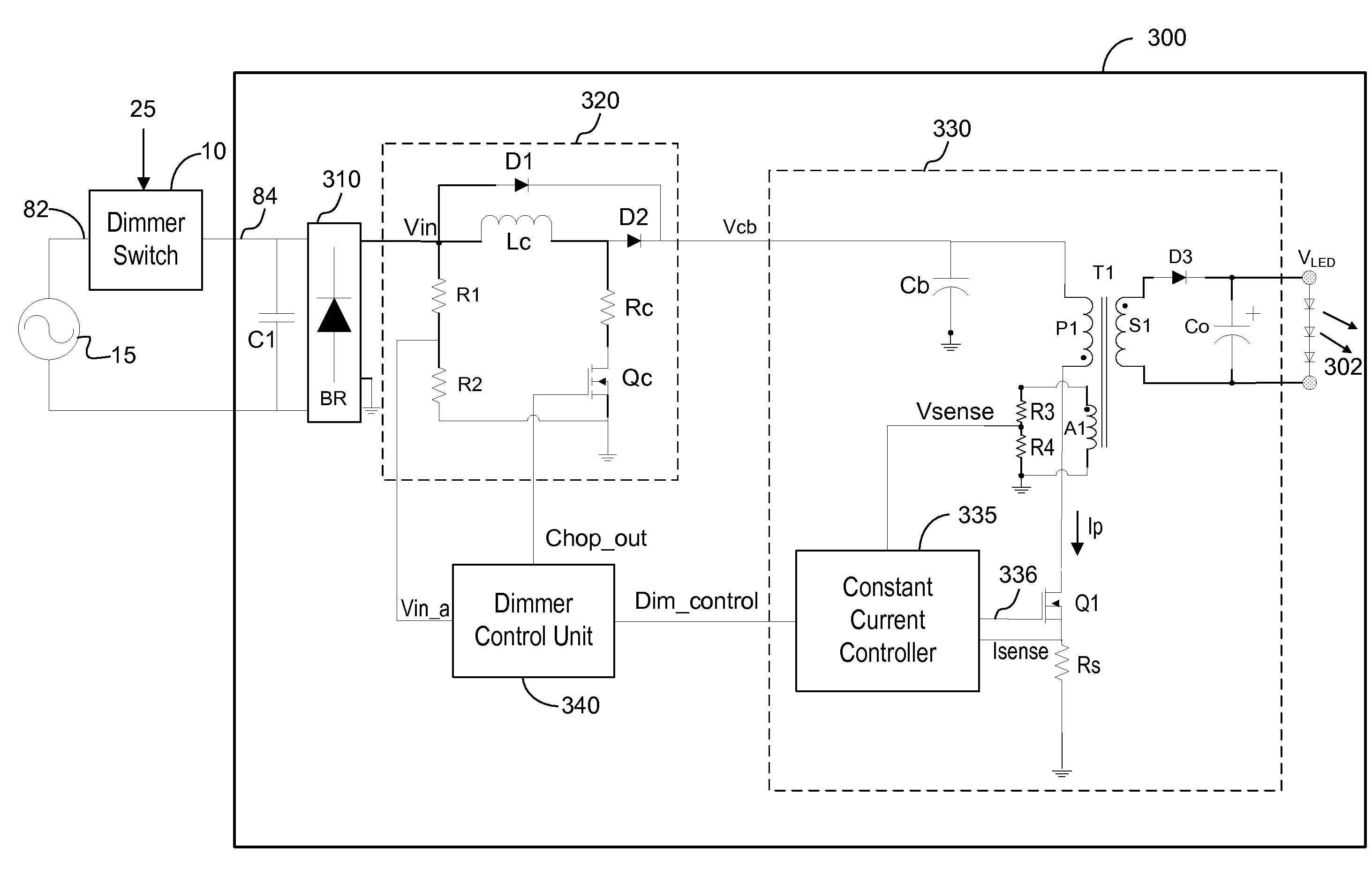
[0013]In one embodiment, the dimmer control unit comprises a phase detector that determines a detected phase angle modulation of the input voltage representative of the detected dimming amount. The phase detector uses the detected dimmer type to determine threshold values and compares the threshold values to the input voltage to determine the phase angle modulation. A chop generator circuit uses the detected phase angle modulation to generate a chopping control signal that controls switching of a chopping circuit for efficiently providing supply power to the power converter. A dimming controller uses the detected phase angle modulation to generate control signals for controlling switching of the power converter to achieve the desired dimming effect.
[0016]The LED lamp according to various embodiments of the present invention has the advantage that the LED lamp can be a direct replacement of conventional incandescent lamps in typical wiring configurations found in residential and commercial building lighting applications, and that the LED lamp can be used with conventional dimmer switches that carry out dimming by changing the input voltage.

Problems solved by technology

Furthermore, LED lamps represent lower environmental impact compared to fluorescent lighting systems (fluorescent ballast combined with fluorescent lamp) that may cause mercury contamination as a result of fluorescent lamp disposal.
However, conventional LED lamps cannot be direct replacements of incandescent lamps and dimmable fluorescent systems without modifications to current wiring and component infrastructure that have been built around incandescent light bulbs.
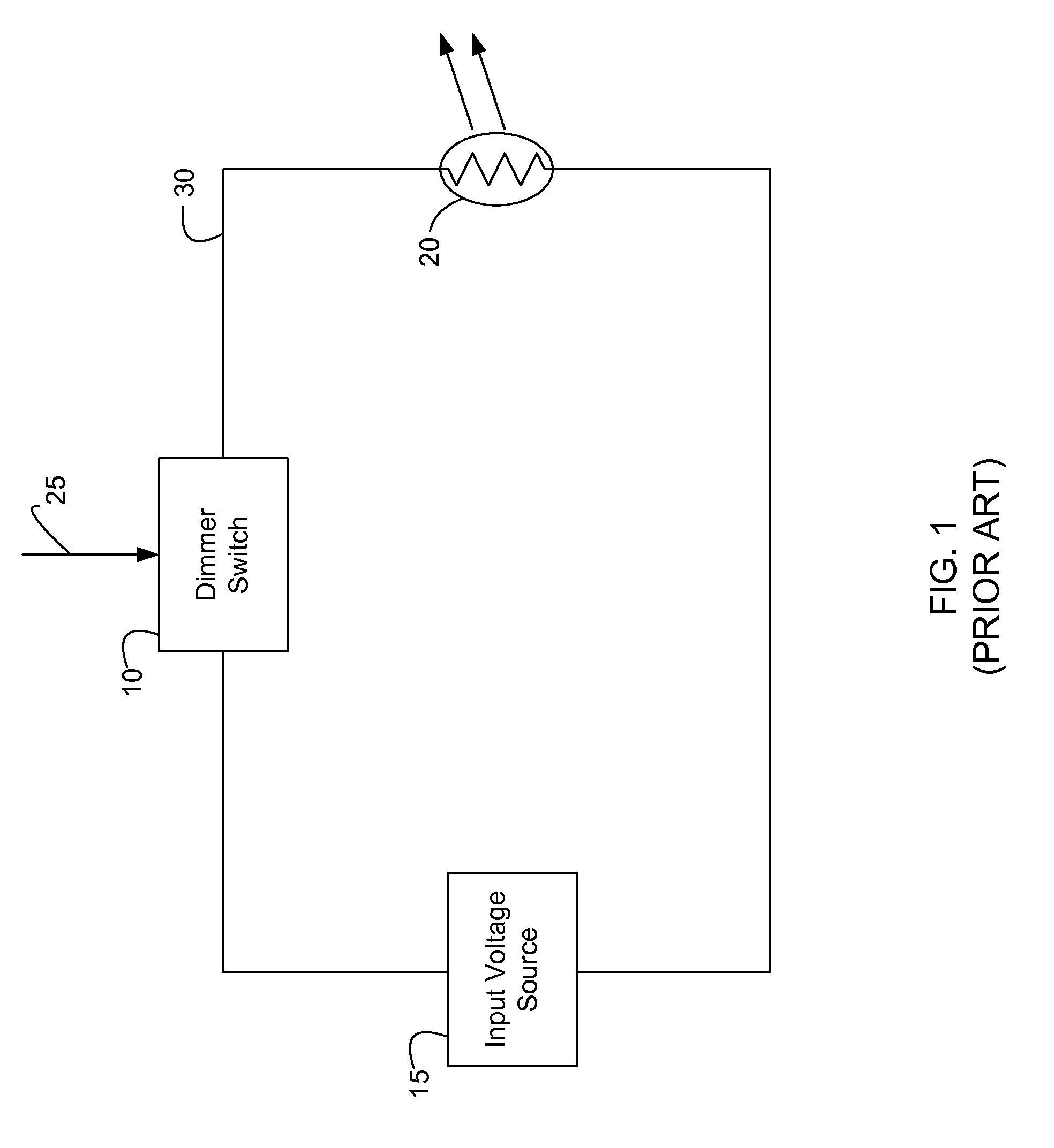
However, conventional dimmer switches that control the phase angle of the input voltage are not compatible with conventional LED lamps, since LEDs, and thus LED lamps, are current driven devices.
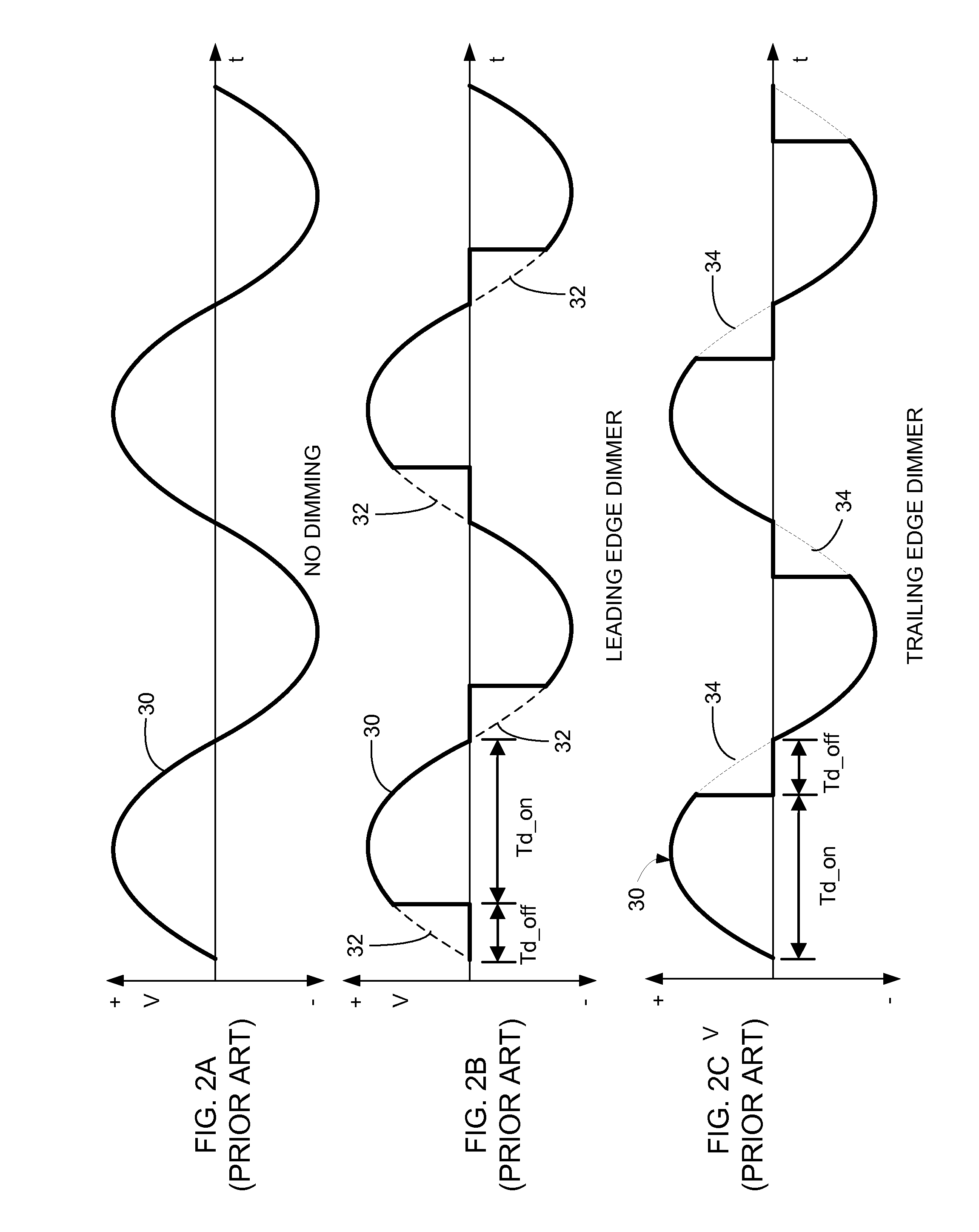
If an LED lamp designed for use with a leading edge dimmer switch is connected to a lamp input voltage 30 using a trailing edge dimmer switch or vice versa, the LED lamp will likely malfunction and / or fail.

Method used


Image

  • Adaptive dimmer detection and control for LED lamp
  • Adaptive dimmer detection and control for LED lamp
  • Adaptive dimmer detection and control for LED lamp

Examples


Embodiment Construction

[0029]The Figures (FIG.) and the following description relate to preferred embodiments of the present invention by way of illustration only. It should be noted that from the following discussion, alternative embodiments of the structures and methods disclosed herein will be readily recognized as viable alternatives that may be employed without departing from the principles of the claimed invention.

[0030]Reference will now be made in detail to several embodiments of the present invention(s), examples of which are illustrated in the accompanying figures. It is noted that wherever practicable similar or like reference numbers may be used in the figures and may indicate similar or like functionality. The figures depict embodiments of the present invention for purposes of illustration only. One skilled in the art will readily recognize from the following description that alternative embodiments of the structures and methods illustrated herein may be employed without departing from the pr...


PUM


Abstract

An LED lamp is provided in which the output light intensity of the LEDs in the LED lamp is adjusted based on the input voltage to the LED lamp. A dimmer control unit detects a type of dimmer switch during a configuration process. Using the detected dimmer type, the dimmer control unit generates control signals appropriate for the detected dimmer type to provide regulated current to the LEDs and to achieve the desired dimming effect. The LED lamp can be a direct replacement of conventional incandescent lamps in typical wiring configurations found in residential and commercial building lighting applications that use conventional dimmer switches.

Description

BACKGROUND OF THE INVENTION[0001]1. Field of the Invention[0002]The present invention relates to driving LED (Light-Emitting Diode) lamps and, more specifically, to dimming the LED lamps.[0003]2. Description of the Related Arts[0004]LEDs are being adopted in a wide variety of electronics applications, for example, architectural lighting, automotive head and tail lights, backlights for liquid crystal display devices, flashlights, etc. Compared to conventional lighting sources such as incandescent lamps and fluorescent lamps, LEDs have significant advantages, including high efficiency, good directionality, color stability, high reliability, long life time, small size, and environmental safety.[0005]The use of LEDs in lighting applications is expected to expand, as they provide significant advantages over incandescent lamps (light bulbs) in power efficiency (lumens per watt) and spectral quality. Furthermore, LED lamps represent lower environmental impact compared to fluorescent lighti...

Claims


Application Information

Patent Timeline
Patent Type & Authority Applications(United States)
IPC IPC(8): H05B37/02H05B44/00
CPCH05B33/0815H05B33/0845Y02B20/347H02M1/4225H02M3/33523H05B45/10Y02B20/30Y02B70/10H05B45/385H02M1/007
Inventor ZHENG, JUNJIEKESTERSON, JOHN W.MYERS, RICHARD M.CHEN, BAORONGCHEN, GORDON
Owner DIALOG SEMICONDUCTOR INC
Learn More