
User interface indicators for changed user interface elements

a technology of user interface and user interface elements, applied in the field of computer processing systems, can solve problems such as software test engineers often facing various challenges, software program crashes, and various challenges

Inactive Publication Date: 2011-01-13
IBM CORP
View PDF16 Cites 268 Cited by
  • Summary
  • Abstract
  • Description
  • Claims
  • Application Information

AI Technical Summary

Benefits of technology

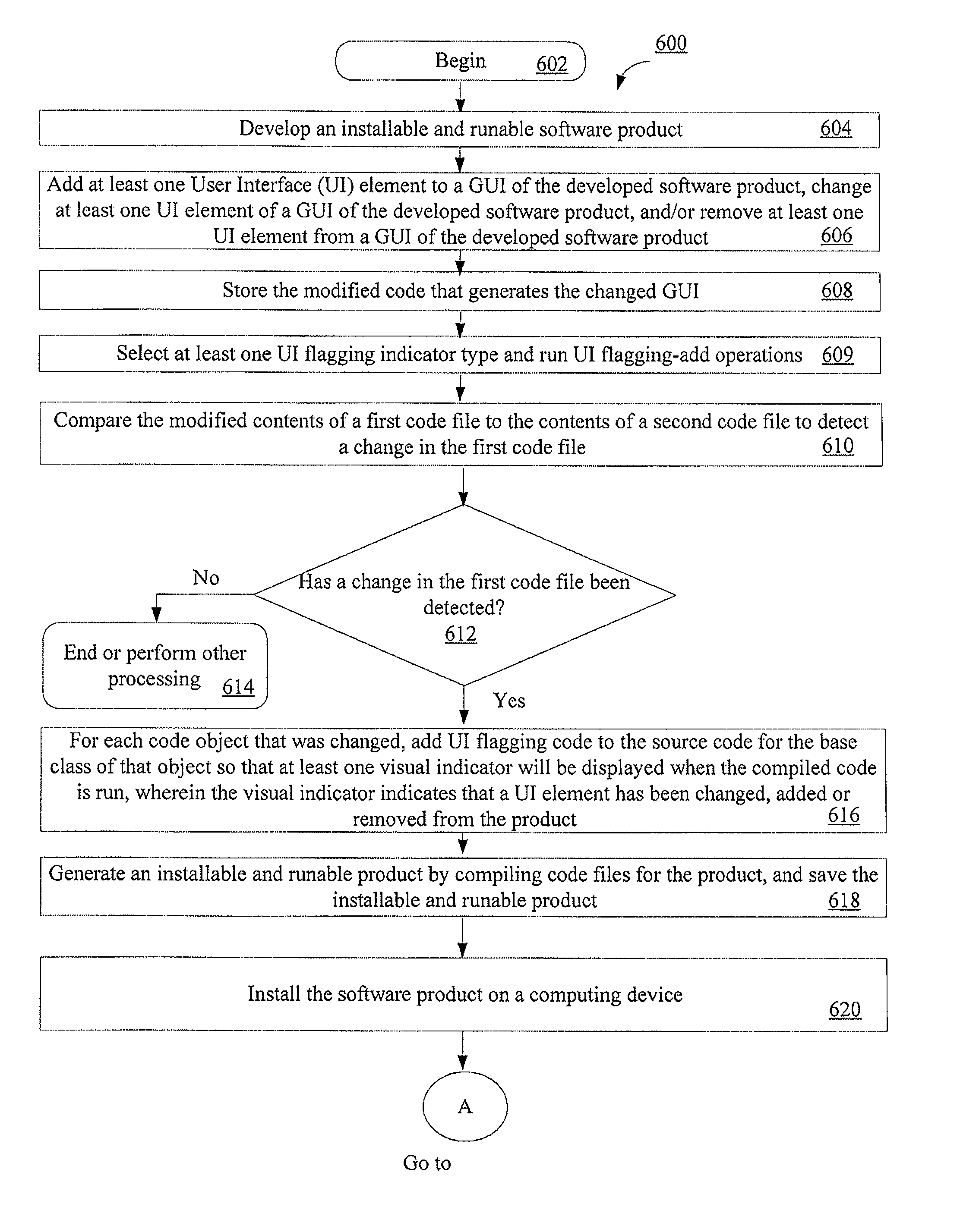
[0012]Upon the occurrence of certain events or acts (e.g., the clicking of a button), the UI flagging indicators can be removed from the UI. Also, a UI flagging setting can be removed from a software development project. Further, information can be collected that is useful for building a record of visual indicators for each build of an application.

Problems solved by technology

The software test engineers often face various challenges when performing FVTs, SVTs, GVTs and / or other types of software testing processes.
Various challenges occur between code drops.
An exemplary defect occurs when a mouse click on a “FileOpen” button causes a software program to crash.

Method used


Image

  • User interface indicators for changed user interface elements
  • User interface indicators for changed user interface elements
  • User interface indicators for changed user interface elements

Examples


example 1

[0069]Lets assume that there is a button on a first page of a UI application called “Send”. The original lines of source code for this button read as follows.

Button sendButton = new Button(“Send”, “firstPage_Send”);frontPage.add(sendButton, “bottom”);

The first line of source code creates a button instance called sendButton that is to be displayed with the word “Send” thereon. Also, the firstPage_Send word is a unique identifier that distinguishes this “Send” button from all other UI elements of the UI application. The second line of source code adds the “Send” button to the first page of the UI application so that it will be displayed on the bottom thereof.

[0070]At a later date, a user (e.g., a software developer) of a computing device (e.g., the computing device 102 of FIG. 1) changes the text displayed on the button. The modified lines of source code for the button read as follows.

Button sendButton = new Button(“Go”, “firstPage_Send”);frontPage.add(sendButton, “bottom”);

As can be ...

example 2

[0074]Lets assume that that a software developer changes a source code text file by adding a new UI element thereto. The source code for the added UI element reads as follows.

Button closeButton = new Button(“Close”, “firstPage_Close”);frontPage.add(closeButton, “bottom”);

The first line of source code creates a button instance called closeButton that is to be displayed with the word “Close” thereon. Also, the firstPage_Close word is a unique identifier that distinguishes this “Close” button from all other UI elements of the UI application. The second line of source code adds the “Close” button to the first page of the UI application so that it will be displayed on the bottom thereof. FilePage is an example of a container object because it has reference to, or “contains”, the closeButton object.

[0075]Using simple file comparison, changes in the source code is detected from the button UI element. Next, UI flagging code is added to the base Button class constructor(s). The UI flagging c...


PUM


Abstract

Systems and methods for user interface (UI) flagging. The methods involve setting a first visual indicator on or adjacent to a first UI element of a UI when code that generates the first UI element has been added to an application or modified so as to change at least one functional characteristic of the first UI element. The methods also involve setting a second visual indicator on a first UI object of the application when code that generates the first UI object has been modified so as to remove a second UI element therefrom. The visual indicators are set by adding UI flagging code to the code that generates the first UI element and / or first UI object. Also, third visual indicators can be set on or adjacent to second UI objects that have “trails” to the first UI element and / or the first UI object.

Description

BACKGROUND[0001]1. Statement of the Technical Field[0002]The present invention relates to computer processing systems. More particularly, the present invention relates to systems and methods for setting user interface indicators on user interface elements of a user interface when code that generates the user interface elements is changed.[0003]2. Description of the Related Art[0004]In code development across all software development, there is a general process that is followed by software developers. First, the software developers write code. The term “code”, as used herein, refers to the symbolic arrangement of data or instructions in a computer program or the set of such instructions. At various stages, the code is implemented in an installable and runable product. The installable and runable product is given to one or more groups of software test engineers. The groups of software test engineers typically include Functional Verification Test (FVT) engineers, System Verification Te...

Claims


Application Information

Patent Timeline
Patent Type & Authority Applications(United States)
IPC IPC(8): G06F3/00
CPCG06F8/34
Inventor MERRILL, ETHAN K.BENNETT, VALERIE M.
Owner IBM CORP
Learn More