
Exercise device weight for mounting to a lifting bar

a technology for lifting bars and exercise devices, which is applied in the direction of weights, sport apparatus, dumbbells, etc., can solve the problems of space and cost restrictions, limit the number of different types of training equipment, dumbbells or barbells, and user injury risk

Inactive Publication Date: 2011-01-13
ESCAPE FITNESS
View PDF8 Cites 14 Cited by
  • Summary
  • Abstract
  • Description
  • Claims
  • Application Information

AI Technical Summary

Benefits of technology

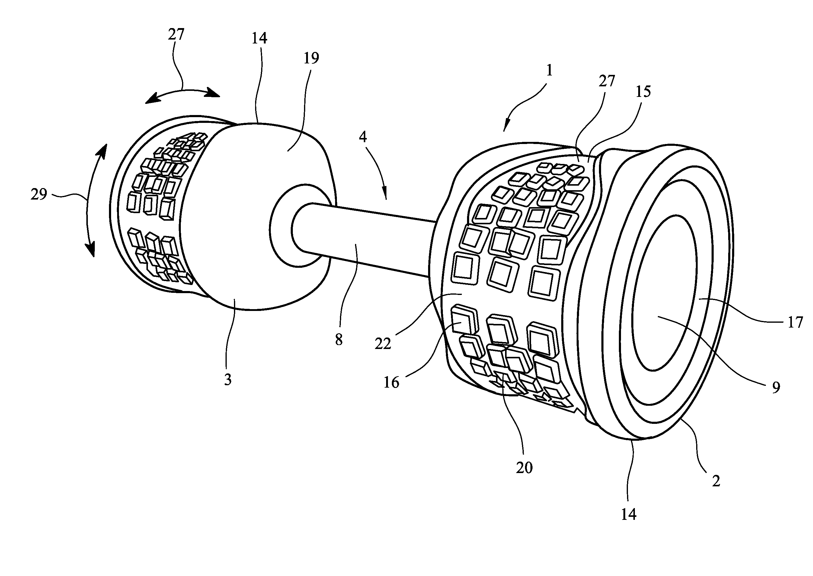
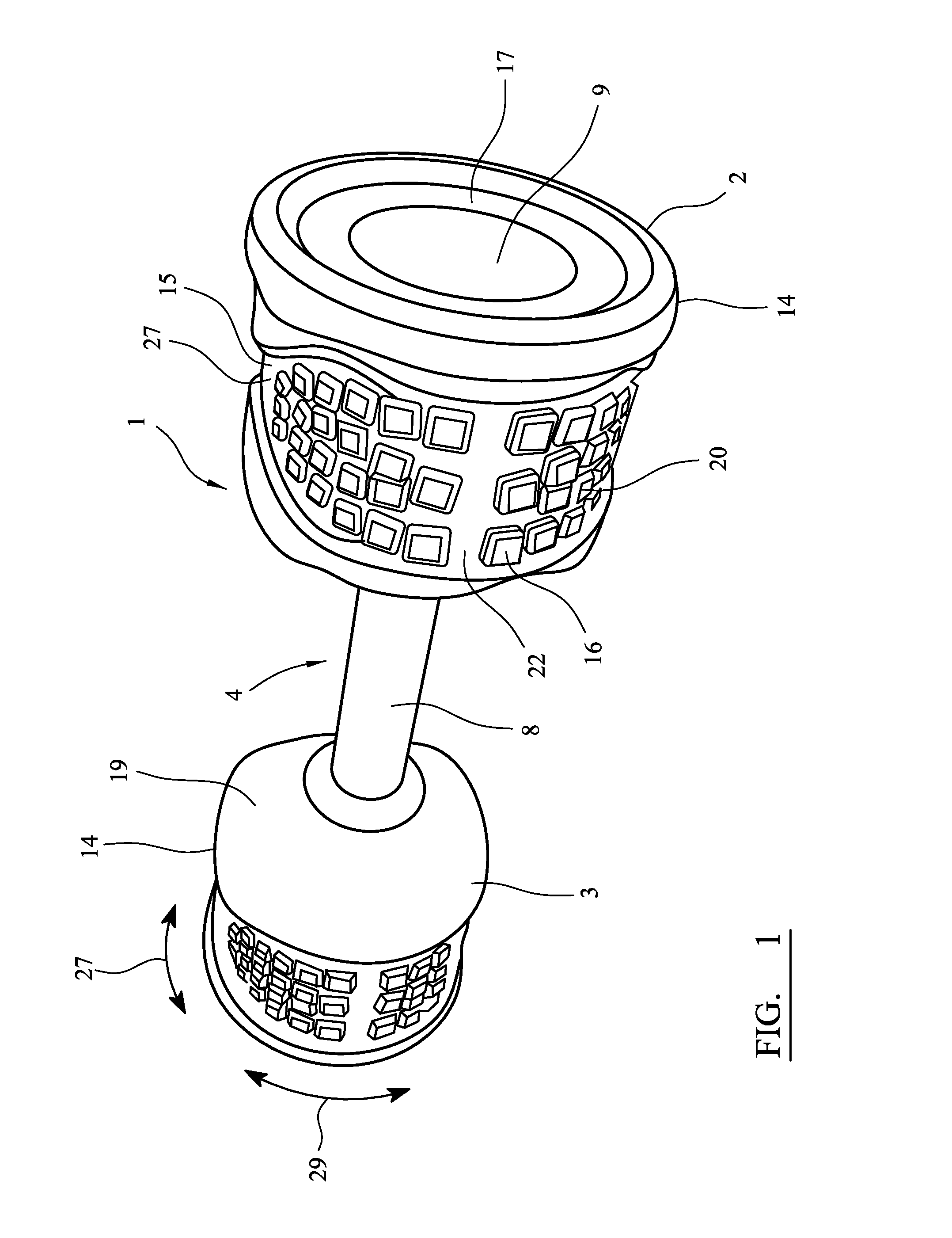
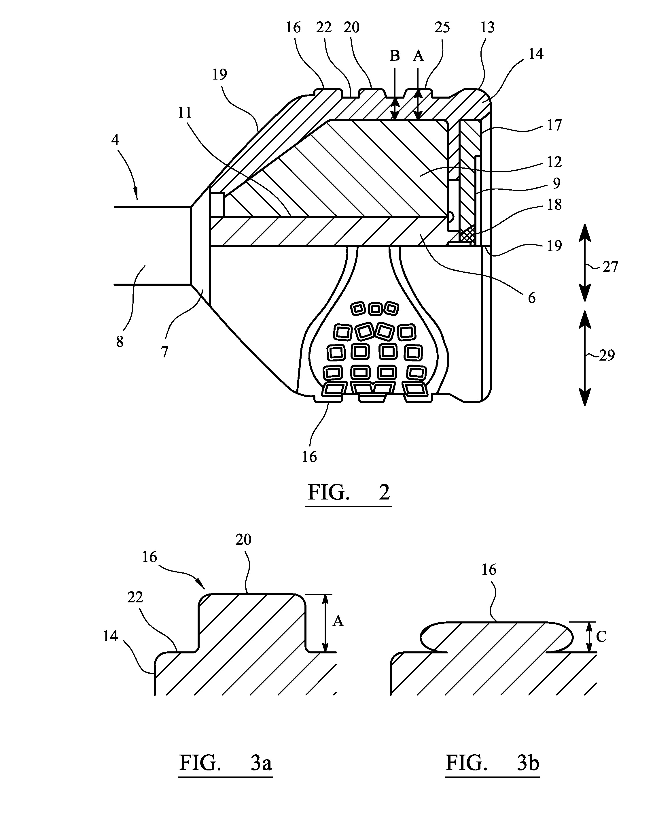
[0014]The resilient projections improve the impact absorption properties of the outer skin and hence of the weight section and exercise device. Specifically, compression of the projections during impact of the weight section with the ground acts to absorb the impact energy and increase deceleration time during impact, thereby providing a “softer” impact. This softer impact reduces jarring of the weight section, and of the fixings between the weight section and the handle of the exercise device to which the weight section is mounted, thereby mitigating the risk of loosening of the weight heads, mitigating damage to the weight section, and reducing damage to the exercise device, for example dumbbell generally, and to other equipment.
[0033]The mold preferably comprises at least two mold sections, or mold halves which are separable to allow the weight section to be placed within and removed there from. This two part mold arrangement enables the weight section to be easily removed from the mold after molding by separating the two mold sections, which would not be possible with a one piece mold due to the projections extending into the mold walls.

Problems solved by technology

However, space and cost restrictions limit the number of different types of training equipment which a gym or fitness club may purchase and store.
A further problem associated with conventional dumbbells or barbells arises when they are dropped to the floor after use.
Over time, repeated dropping can lead to the weight heads becoming noticeably loose, or even falling off the handle, resulting in a risk of injury to the user.
The increase in the number of gym members, and therefore the increasing frequency with which such weights are used, significantly accelerates this process, which greatly reduces the life cycle of the dumbbells, and can lead to damage of the associated equipment such as racks and benches, and can cause unnecessary wear to the flooring.

Method used


Image

  • Exercise device weight for mounting to a lifting bar
  • Exercise device weight for mounting to a lifting bar
  • Exercise device weight for mounting to a lifting bar

Examples


second embodiment

[0062]the invention is shown in FIGS. 4 to 6. In this embodiment like reference numerals are used to indicate the like features. This embodiment and dumbbell is generally similar to that described above and shown in FIGS. 1 to 3 and so only the main difference will be described in detail.

first embodiment

[0063]In particular in this embodiment the projections 16 now comprise a series of tapering circumferentially extending ribs 30,32,34. These comprise a longer central rib 32 and two shorter ribs 30 and 34 disposed axially either side of the central rib 32 and which do not extend circumferential as far around the weight section 2. There is also a further axially extending projection 36. Again as in the first embodiment the projections 16 are only disposed and extend over and around part 29 of the circumference of the weight section 2 and there is a region 27 where there are no projections 16 as most clearly shown in FIG. 6.

[0064]In this embodiment there is also a pair (although in other embodiments there may be only one) of recesses 40 defined in each the weight section 2, and defining an axially facing shoulder surface 42. These recesses 40 are located diametrically opposite each other on each weight section 2 and extend over and around only part of the circumference of the weight s...


PUM


Abstract

An exercise device weight section (2) for mounting to a lifting bar (4) of an exercise device (1), in particular a dumbbell or bar bell. The weight section (2) having an outer circumferential surface (15) comprising an outer skin (14) at least partially around the outer circumferential surface of the weight section (2) comprising a plurality of resilient projections (16) extending from at least part of the outer circumferential surface of the weight section (2). The plurality of projections (16) are disposed only in a discrete circumferential region (29) of the circumferential surface of the weight section (2). The projections (16) provide improved impact absorption when the weight section (2) is dropped protecting the weight section, floor and associated equipment form damage, and also reduce loosening of the mounting of the weight section on the bar (4). The projections (16) also provide areas of improved grip allowing the weight section and exercise device to be better gripped and lifted. Recesses (40) may also be defined in the weight sections to further define handles for gripping the weight section (2).

Description

BACKGROUND OF THE INVENTION[0001]1. Field of the Invention[0002]The present invention relates to an exercise device and in particular to a dumbbell or barbell for weight lifting and other fitness activities. More specifically it relates to the weight sections for mounting to a lifting bar in such exercise devices.[0003]2. Related Art[0004]Conventional dumbbells or barbells comprise a bar and a set of weights mounted on the ends of the bar. The dumbbell or barbell is lifted by the handle bar in order to train specific muscles groups, and / or increase muscle mass. The weights may be permanently fixed, for example in a dumbbell, or may be removably mounted so as to alter the weight in a barbell type arrangement but also in some dumbbell arrangements.[0005]An increase in the popularity of fitness training has resulted in the development of many new training programs and classes, to cater for a broad spectrum of training requirements. As such, increasingly varied weight training equipment...

Claims


Application Information

Patent Timeline
Patent Type & Authority Applications(United States)
IPC IPC(8): A63B21/072A63B21/06
CPCA63B2071/0063A63B21/0726A63B21/072
Inventor JANUSZEK, RICHARD ZDZISLAW
Owner ESCAPE FITNESS
Learn More