
Display panel and driving method thereof

a technology of display panel and driving method, which is applied in the direction of electric digital data processing, instruments, computing, etc., can solve the problems of reducing affecting the brightness of pixels, and affecting the display quality, so as to enhance the display quality and reduce the number of data lines

Inactive Publication Date: 2011-01-13
CHUNGHWA PICTURE TUBES LTD
View PDF5 Cites 6 Cited by
  • Summary
  • Abstract
  • Description
  • Claims
  • Application Information

AI Technical Summary

Benefits of technology

[0005]Therefore, an aspect of the present invention is to provide a display panel and a driving method thereof to reduce the number of the data lines, thereby reducing the manufacturing cost.
[0006]Another aspect of the present invention is to provide a display panel and a driving method thereof to improve line defect, thereby enhancing the display quality.
[0009]Therefore, with the use of the display panel and the driving method thereof disclosed in the embodiments of the present invention, the number of the data lines can be reduced, and the problem of the brightness difference of the pixels can be improved to enhance the display quality.

Problems solved by technology

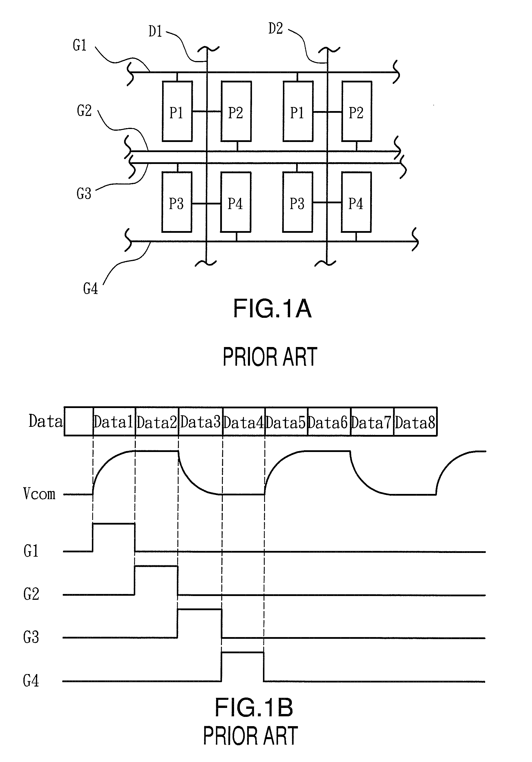
However, the signals (such as the common voltage Vcom or the gate signals Gate1-Gate4) received by the pixels P1-P4 are not ideal waveforms (such as square waveforms), therefore resulting in an abnormality of the displaying images.
Therefore, when the gate lines G1 and G3 are turned on, the common voltage Vcom is still charging or discharging, resulting in an incomplete charging of the LCD cell, and the deflection of the liquid crystal molecules can not be controlled perfectly, resulting in the brightness difference of the pixels.
Furthermore, the brightness difference of the pixels is susceptible to occur on the same pixel row, such as G1, G3, or G2, G4, resulting in a line defect.
Namely, the unexpected bright lines or dark lines occurred on the screen may thereby affect the display quality.

Method used


Image

  • Display panel and driving method thereof
  • Display panel and driving method thereof
  • Display panel and driving method thereof

Examples


Embodiment Construction

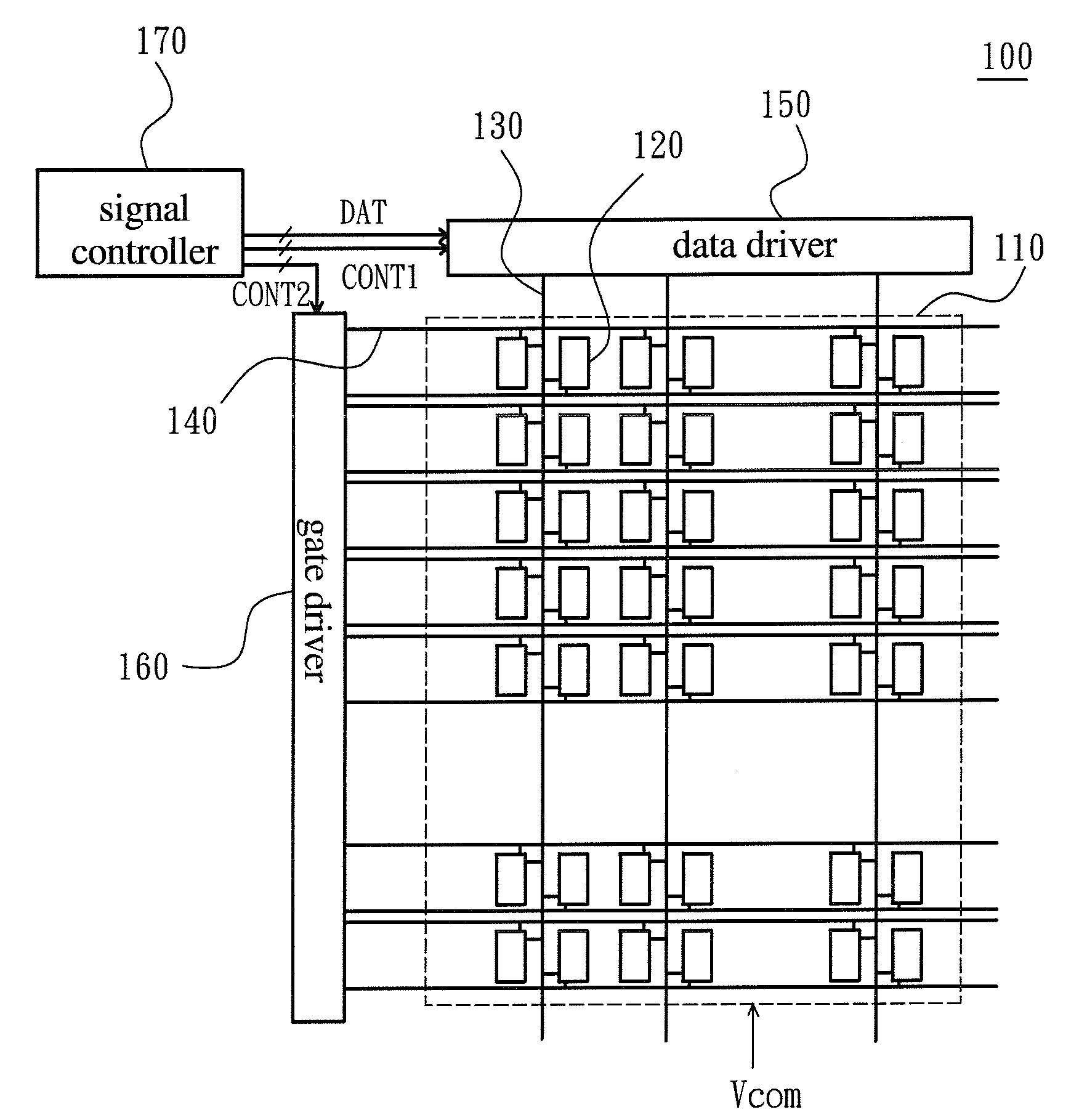
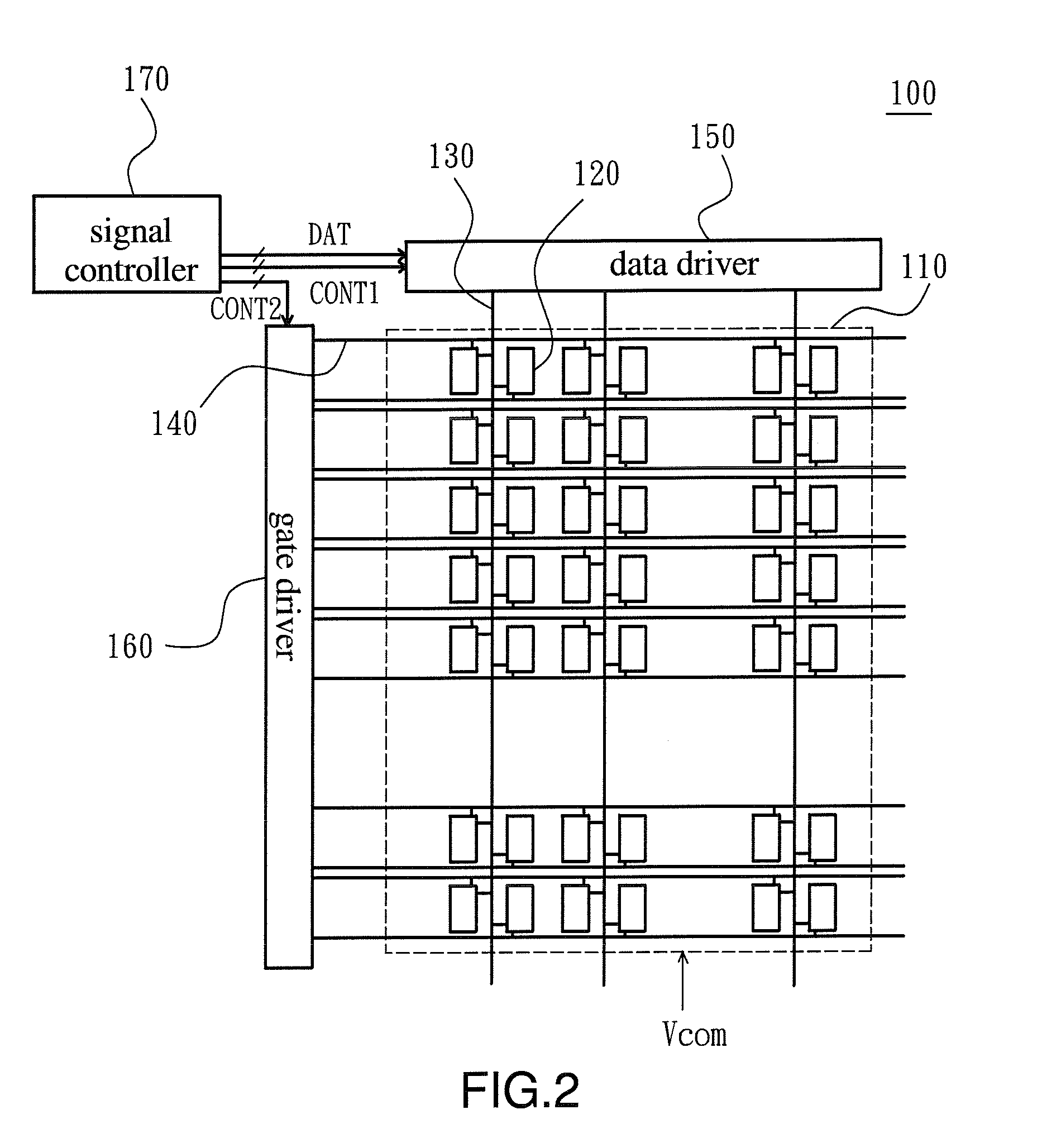
[0019]In order to make the illustration of the present invention more explicit and complete, the following description is stated with reference to FIG. 2 through FIG. 7.

[0020]Referring to FIG. 2, presented herein is a schematic view showing a display panel according to one embodiment of the present invention. The display panel 100 and the driving method thereof can be applicable to a display apparatus, such as a liquid crystal display (LCD), an organic light emitting diode (OLED) display, a plasma display panel (PDP) or a field emission display (FED). Taking the LCD for example, the display panel 100 may be an LCD panel assembled with a backlight module, thereby forming the LCD.

[0021]Referring to FIG. 2 again, the display panel 100 of the present embodiment comprises a substrate 110, a plurality of pixel rows 120, a plurality of data lines 130, a plurality of gate lines 140, a data driver 150, a gate driver 160 and a signal controller 170. The data lines 130 and the gate lines 140 a...


PUM


Abstract

A display panel and a driving method thereof are disclosed. The display panel comprises a plurality of pixel rows, a plurality of data lines and a plurality of gate lines. Each of the pixel rows includes pairs of first and second pixels adjacent to each other. The data lines are positioned between the first and the second pixels, respectively. The gate lines include first, second, third and fourth gate lines arranged in an alternating manner. The method comprises the following steps: turning on the gate lines in a sequence of first, second, fourth and third gate lines; and transmitting the data signal to the pixels through the data lines. The panel is applicable to an LCD panel and an LCD apparatus.

Description

FIELD OF THE INVENTION[0001]The present invention relates to a display panel and a driving method thereof, and more particularly, to a display panel and a driving method for reducing the number of data lines.BACKGROUND OF THE INVENTION[0002]Currently, a display panel, such as a liquid crystal display (LCD) panel or an organic light emitting diode (OLED) display panel, comprises a bottom glass substrate having a plurality of pixels and a plurality of signal lines, such as scanning lines and data lines. Each of the pixels receives the control signals, such as scanning signals and pixel voltage, from the corresponding signal line, thereby displaying image.[0003]Refer to FIG. 1A and FIG. 1B. FIG. 1A is a partial schematic diagram showing a conventional display panel, and FIG. 1B shows waveforms of signals for the conventional display panel. As shown in FIG. 1A, the display panel includes a plurality of gate lines G1-G4, a plurality of data lines D1, D2 and a plurality of pixels P1-P4. A...

Claims


Application Information

Patent Timeline
Patent Type & Authority Applications(United States)
IPC IPC(8): G09G5/00G09G3/30G09G3/20G09G3/36
CPCG09G3/3614G09G2300/0426G09G3/3655
Inventor CHANG, SHU-MINGHUANG, MING-WEILIU, HSIANG-LUN
Owner CHUNGHWA PICTURE TUBES LTD
Learn More