
Device for sealing a component housing in a motor-vehicle drive train

a technology for component housings and drive trains, which is applied in the direction of dynamo-electric machines, electric energy vehicles, and closures, etc., can solve the problems of relative complexity of control or regulation, and achieve the effects of preventing dust ingress reliably, reliable build-up of pressure, and positive pressur

Active Publication Date: 2011-01-13
DR ING H C F PORSCHE AG
View PDF2 Cites 0 Cited by
  • Summary
  • Abstract
  • Description
  • Claims
  • Application Information

AI Technical Summary

Benefits of technology

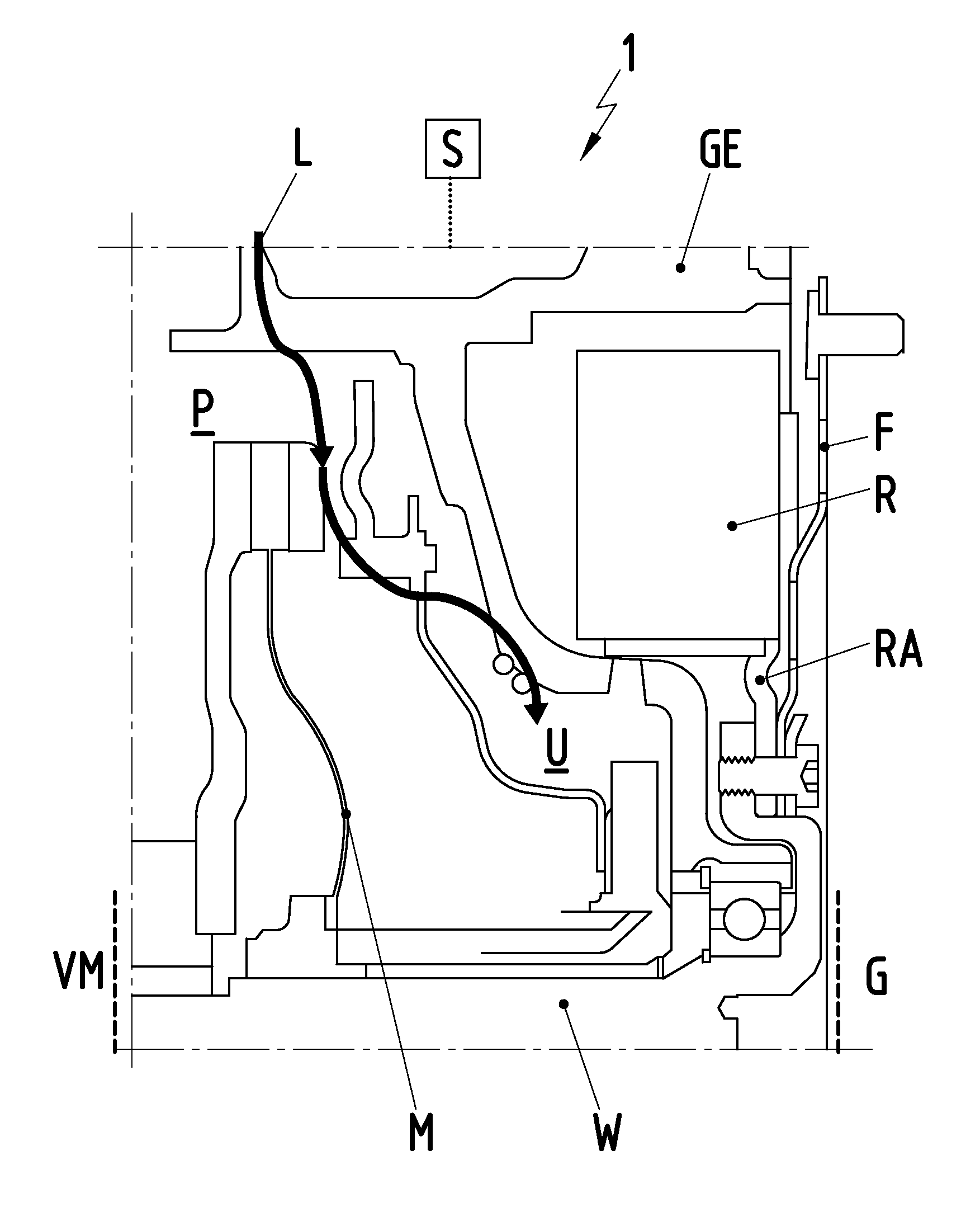
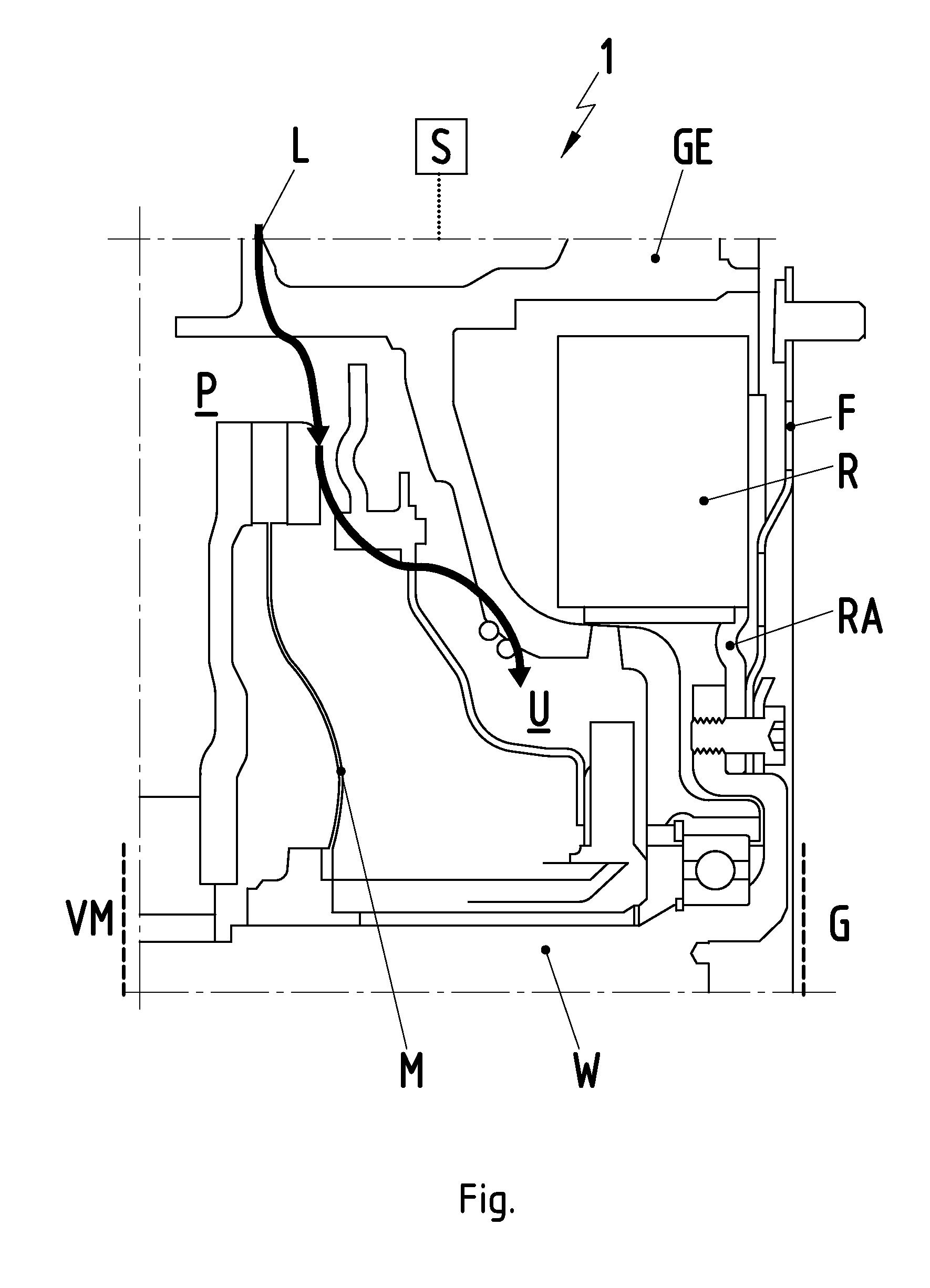
[0009]The invention uses a rotating component of the hybrid module to pressurize the interior of the housing of the hybrid module. The rotating component is designed similar to an impeller of a centrifugal pump. Therefore, rotation of the component builds up a positive pressure in the radially outer region thereof in comparison to a radially inner region. More particularly, the invention makes use of the fact that geometries of a hybrid module and a centrifugal pump are similar. Both of these geometries have a rotating component mounted in a housing. The rotating component of the hybrid module is designed analogously to the impeller of a centrifugal pump, and a corresponding effect also is produced in the hybrid module. The rotating component is coupled mechanically to the drive train and rotates whenever the drive train rotates. However, the drive train is driven by the electric motor to rotate virtually continuously during operation of the motor vehicle, the combustion engine and / or by kinetic energy of the motor vehicle (recuperation). Thus, complicated control or regulation of the pressurization of the housing interior of the hybrid module is no longer necessary. Specifically, the rotating component of the hybrid module is an impeller, and pressurization by the virtually continuous rotation of the drive train during operation of the motor vehicle is provided virtually continuously in the housing interior of the hybrid module. The radially outer region of the rotating component of the hybrid module is in the vicinity of the housing in the interior of the hybrid module. Thus, positive pressure is produced in the housing. Therefore, when the hybrid module is used, for example, in the drive train of an off-road vehicle, the ingress of water during fording a stream or when driving through puddles, and also the ingress of dust reliably are prevented.
[0010]The rotating component preferably is a rotor element of the electric machine, such as a rotor of the electric machine or a rotor connection of the electric machine to the drive train. For example, an external rotor rotates about a fixed stator. In the case of a single-shaft parallel hybrid, the stator is near an extension of the crank shaft of the combustion engine. The rotor of the electric machine therefore rotates about an axial extension of the crank shaft. The rotor may be connected to the drive train via a rotor hub. The rotor hub may be designed suitably in the form of an impeller of a centrifugal pump by, for example providing impeller blades. Thus, there is a reliable build up of pressure in the radially outer region of the rotor element in comparison to the radially inner region thereof. The radially outer region is arranged near the housing of the hybrid module. Therefore, the hybrid module reliably is pressurized when the motor vehicle is in operation, i.e. when the drive train rotates.
[0016]A pressure accumulator can be used for the positive pressure provided in each case by the actuator. Thus, the pressure peaks are smoothed and the hybrid module is pressurized uniformly without complicated control or regulation.

Problems solved by technology

In addition, relatively complicated control or regulation is necessary to connect the compressed-air source to the housing interior when the need arises.

Method used


Image

  • Device for sealing a component housing in a motor-vehicle drive train
  • Device for sealing a component housing in a motor-vehicle drive train

Examples


Embodiment Construction

[0019]The FIGURE shows a hybrid module 1 of a single-shaft parallel hybrid arranged between the combustion engine VM to the left of the hybrid module 1 and a torque converter or gearing G to the right of the hybrid module 1. The hybrid module 1 has a shaft W and is illustrated as a section only in its part located above the shaft W. A housing GE is provided radially outside the shaft W. The shaft W of the single-shaft parallel hybrid extends from the combustion engine VM via the hybrid module 1 as far as the gearing G of the drive train. An electric machine with a rotor R is encompassed by the hybrid module 1. The rotor R is coupled mechanically to the shaft W via the rotor connection RA.

[0020]When the electric machine is operated as a motor, the rotor R is supplied with electric current and rotates about the shaft W to drive the drive train. When the electric machine is operated as a generator, the shaft W rotates and carries along the rotor R via the rotor connection RA, and there...


PUM


Abstract

A component housing in a motor-vehicle drive train is sealed by pressurization of the housing interior. The component is a hybrid module (1) comprising at least one electric machine provided between the combustion engine (VM) and the gearing (G) of the motor-vehicle drive train. The pressurization is achieved by a rotating component (R, RA, M, F) of the hybrid module. The rotating component is designed in a manner similar to an impeller of a centrifugal pump. Therefore, rotation of the component builds up a positive pressure (P) on the radially outer region of the rotating component in the region of the housing (GE) in the interior of the hybrid module.

Description

CROSS-REFERENCE TO RELATED APPLICATIONS[0001]This application claims priority under 35 USC 119 to German Patent Application No. 10 2009 032 112.8 filed on Jul. 8, 2009, the entire disclosures of which are incorporated herein by reference.BACKGROUND OF THE INVENTION[0002]1. Field of the Invention[0003]The invention relates to a device for sealing a component housing in a motor-vehicle drive train. The interior of the housing is acted upon with a pressure that is greater than the pressure prevailing outside the housing to prevent media, such as water or mud, is from penetrating to the interior of the housing.[0004]2. Description of the Related Art[0005]GB 801802 and DE 29 42 712 disclose devices for sealing a component case in a motor-vehicle by applying pressure in a housing that is greater than the pressure prevailing outside. These disclosures each use the compressed-air brake system of a utility vehicle as the compressed-air source for pressurization of the housing interior. The d...

Claims


Application Information

Patent Timeline
Patent Type & Authority Applications(United States)
IPC IPC(8): H02K9/06H02K5/10
CPCB60K6/387B60K6/405B60K6/48B60W10/02B60W10/06Y10S277/927B60W20/00B60W2510/0604Y02T10/6221Y02T10/6286B60W10/08Y02T10/62
Inventor SCHIEK, WERNERSAUVLET, NILSSTACHE, IMMO
Owner DR ING H C F PORSCHE AG
Learn More