
Clean room and method for regulating airflow of clean room

a technology for cleaning rooms and clean rooms, applied in ventilation systems, lighting and heating apparatus, heating types, etc., can solve the problems of reducing the cleanliness class of the clean room of the main process, affecting the efficiency of the clean room, and unable to achieve good regulation effect after regulation

Active Publication Date: 2022-07-05
HKC CORP LTD +1
View PDF16 Cites 0 Cited by
  • Summary
  • Abstract
  • Description
  • Claims
  • Application Information

AI Technical Summary

Benefits of technology

Simplifies airflow regulation, prevents pollution in uncleaned process spaces, and maintains cleanliness class by allowing for easy adjustment of airflow channels, reducing the need for frequent FFU regulation.

Problems solved by technology

When the structures of devices are complicated and the main process area (i. e., the clean room area where the process production operation is performed) needs to maintain a positive pressure, the FFU can only be regulated by regional control.
If the demand for maintaining the positive pressure in the main process area is still not achieved, a regional ventilation space is required to be sealed, but such regulation is laborious and the regulation effect achieved after the regulation is not good.
In addition, in the initial stage of equipment installation in the clean room, if the clean function of a semiconductor fabrication plant (FAB, clean room) has not been completed yet, the dust-free space environment (cleanliness class of the clean room is required to achieve Class 100) of the main process clean area is vulnerable to the air pollution from the space of a non-process area (cleanliness class of the clean room is Class 100), which results in decrease in the cleanliness class of the clean room of the main process clean area, and further requires to improve the cleaning frequency of the FFU, which is time-consuming and laborious and would result in serious consequence of affecting the subsequent product yield.

Method used


Image

  • Clean room and method for regulating airflow of clean room
  • Clean room and method for regulating airflow of clean room
  • Clean room and method for regulating airflow of clean room

Examples


Embodiment Construction

[0039]In order to make the objects, technical solutions, and advantages of the present application more clear, the present application will be further described in detail hereinbelow with reference to the accompanying drawings and embodiments. It should be understood that the specific embodiments described herein are merely intended to explain the application rather than to limit the present application.

[0040]It should be noted that when an element is referred to as being “fixed” or “arranged” at / in / on another element, it can be directly or indirectly at / in / on the other element. When an element is referred to as being “connected” to / with another element, it can be directly or indirectly connected to / with the other element.

[0041]It should also be noted that the terms of the left, right, upper, and lower orientations in these embodiments are merely relative concepts or reference to the normal use state of the product, and should not be considered as limitation.

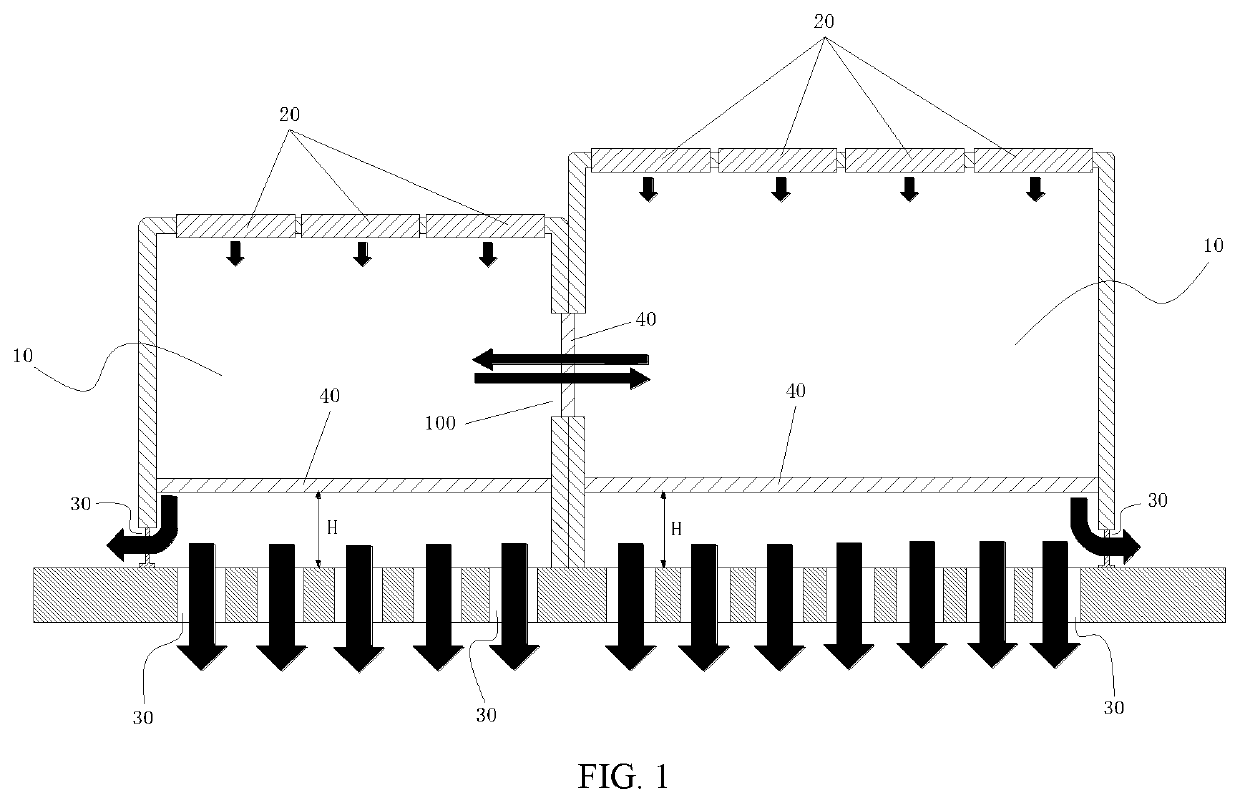
[0042]As shown in FIG. 1...


PUM


Abstract

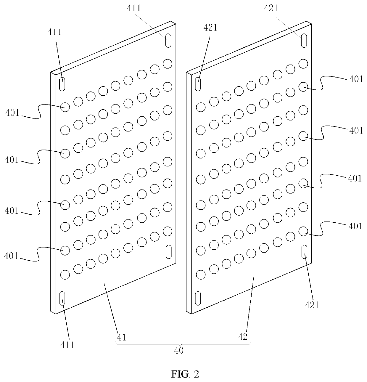
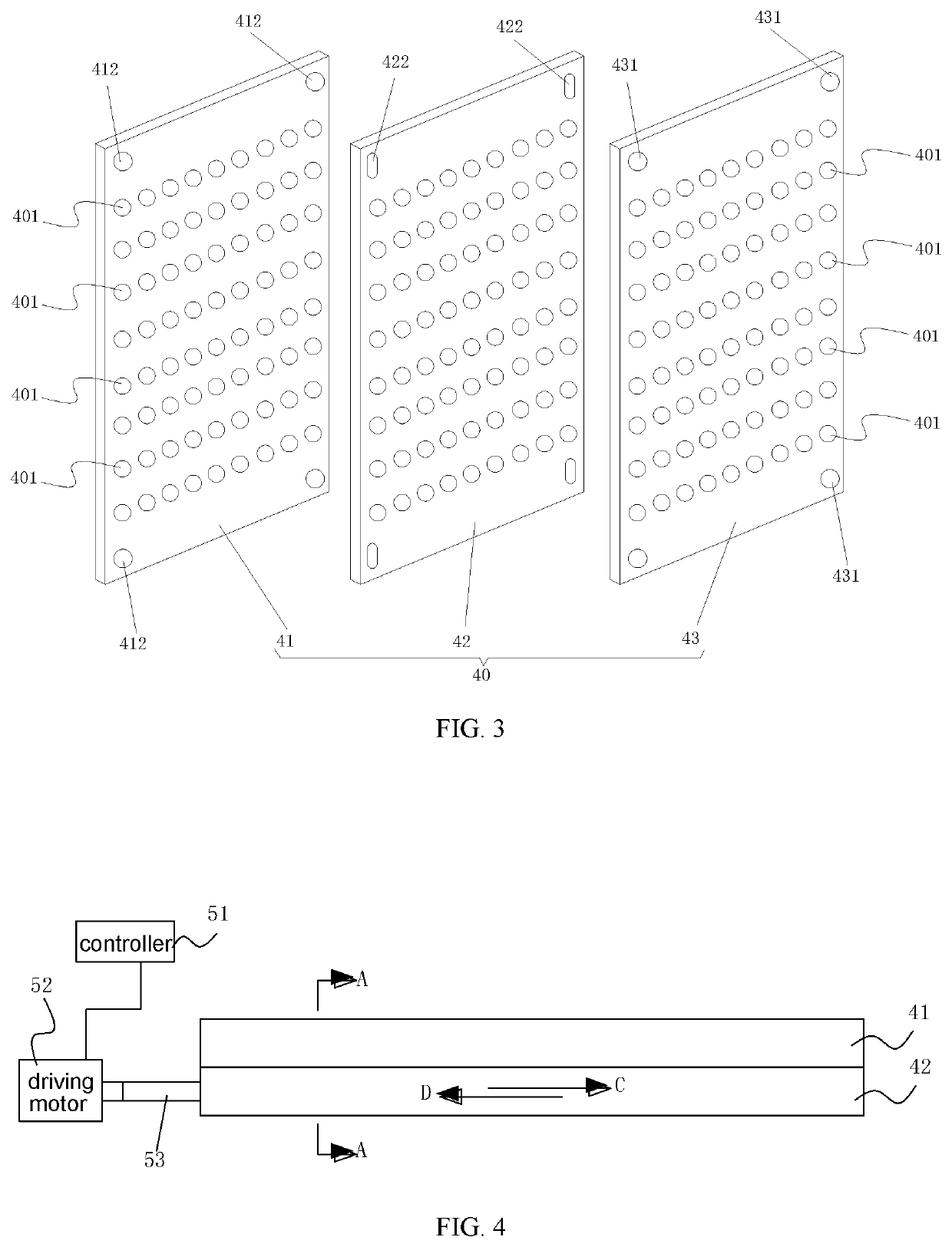
A clean room and a method for regulating an airflow of the clean room. The clean room includes: a plurality of process spaces in communication with one another, and a fan filter unit. The fan filter units is installed at a top of each one of the plurality of process spaces, and a bottom of each of the plurality of process spaces is provided with a ventilation passage. The clean room further includes: an airflow regulation device, configured to regulate an airflow in each of the process spaces; the airflow regulation device is installed inside each of the plurality of process spaces, and is arranged downstream of the respective fan filter unit.

Description

CROSS-REFERENCE TO RELATED APPLICATIONS[0001]This application is the U.S. national phase of International Application No. PCT / CN2017 / 086261 with an international filing date of May 27, 2017, designating the U.S., now pending, and further claims priority benefits to Chinese Patent Application No. 201611109857.2 filed Dec. 6, 2016. The contents of all of the aforementioned applications, including any intervening amendments thereto, are incorporated herein by reference.BACKGROUNDTechnical Field[0002]The present application relates to the technical field of dust-free clean environment technology, and more particularly to a clean room and a method for regulating an airflow of the clean room.Description of Related Art[0003]An area with process cleanliness, i. e., a clean room, adopts a Fan Filter Unit (FFU) to regulate the ventilation frequency in a process space to achieve the required cleanliness (for example, cleanliness class 100, i. e., Class 100 of the clean room). During the regula...

Claims


Application Information

Patent Timeline
Patent Type & Authority Patents(United States)
IPC IPC(8): F24F3/167F24F11/89F24F7/007F24F11/00F24F13/08F24F13/28F24F8/10
CPCF24F3/167F24F7/007F24F11/0001F24F11/89F24F13/082F24F13/28F24F8/10
Inventor HUANG, CHUNCHIN
Owner HKC CORP LTD
Learn More