Material web for use in an absorbent article

a material web and absorbent article technology, applied in the field of material webs for use in absorbent articles, can solve the problems of reducing the liquid-permeability at the bonding, the acquisition rate is much too low to be able to instantaneously, and the cost of materials is high, so as to achieve stable, stable, and good tensile strength. , the effect of improving the tensile strength

Inactive Publication Date: 2011-01-06
SCA HYGIENE PROD AB
View PDF6 Cites 36 Cited by
  • Summary
  • Abstract
  • Description
  • Claims
  • Application Information

AI Technical Summary

Benefits of technology

[0014]The holes and the recesses thus form hour-glass shaped hollows or channels through the material web, which give the material web high liquid-permeability. This liquid-permeability is further increased by the diminishing form of the recesses in the first surface, which results in capillary forces leading received liquid in a direction towards and down into the holes. The presence and shape of the recesses in the second surface contribute in turn to distributing the received liquid over underlying layers in the article, while the cavity created by the recesses prevents liquid present in the absorbent core of the article from rewetting the first surface via the holes. In addition, the recesses and the holes contribute to good ventilation of the material web and the article.
[0030]If it is the case that an ultrasonic horn is used to create both the recesses and the holes, it is advantageous if said ultrasonic horn works against one and the same roll. In this way, a further reduction of the number of elements in the manufacturing device is obtained, which leads to a reduction in production costs compared with using a separate roll for each horn, which is an alternative, but less preferred, possibility. This is also a means of avoiding the synchronisation problems which arise when the material web is to be put onto a second roll prior to forming the holes. In other words, it ensures in a simple manner that the penetrating holes are actually formed in the recesses, thus increasing the quality of the final product. In the same way, it is also advantageous in the case of hot calendering if the forming of the recesses and the holes is carried out against one and the same roll.

Problems solved by technology

Such materials have, certainly, a high absorption capacity; however, in many cases they have an acquisition rate that is much too low to be able to instantaneously absorb the large quantity of liquid which can be emitted in only a few seconds during urination.
However, the material webs obtain a more or less liquid-impermeable character at the bottoms of the recesses, which would lead to reduced liquid-permeability at the bonds.
However, perforating by means of spikes requires that the material layers are fed forward at low speed, especially if stable, round holes are desired, and the slow processes result in expensive materials.
This is a particularly significant problem where the manufacture of disposable articles is concerned, as the cost of materials is very important.
The complexity of the manufacturing process and the wear and tear it puts on the component parts of the manufacturing device also contribute to increasing the production costs.
However, the material web created in this way displays a less stable three-dimensional structure, a relatively low tensile strength and poorer bonding of the layers in the material web.
However, these holes only extend through the upper sheet and a certain distance down into the lower sheet.
However, these solutions also lead to high production costs due to low production speeds, complex manufacturing processes and high wear and tear on components.
Moreover, the holes in the above-described embodiments indeed give the material web greater liquid-permeability but at the same time they allow insufficient distribution of the received liquid over underlying layers in the article.
In addition, there is a risk of rewetting of the surface of the material web that faces towards a user of the article, as liquid present further inside the article forces its way up through the holes.

Method used


Image

  • Material web for use in an absorbent article
  • Material web for use in an absorbent article
  • Material web for use in an absorbent article

Examples


Embodiment Construction

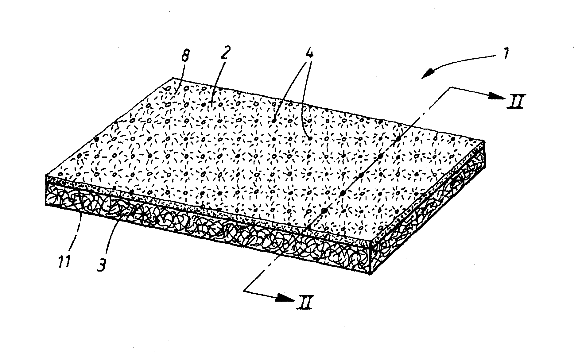
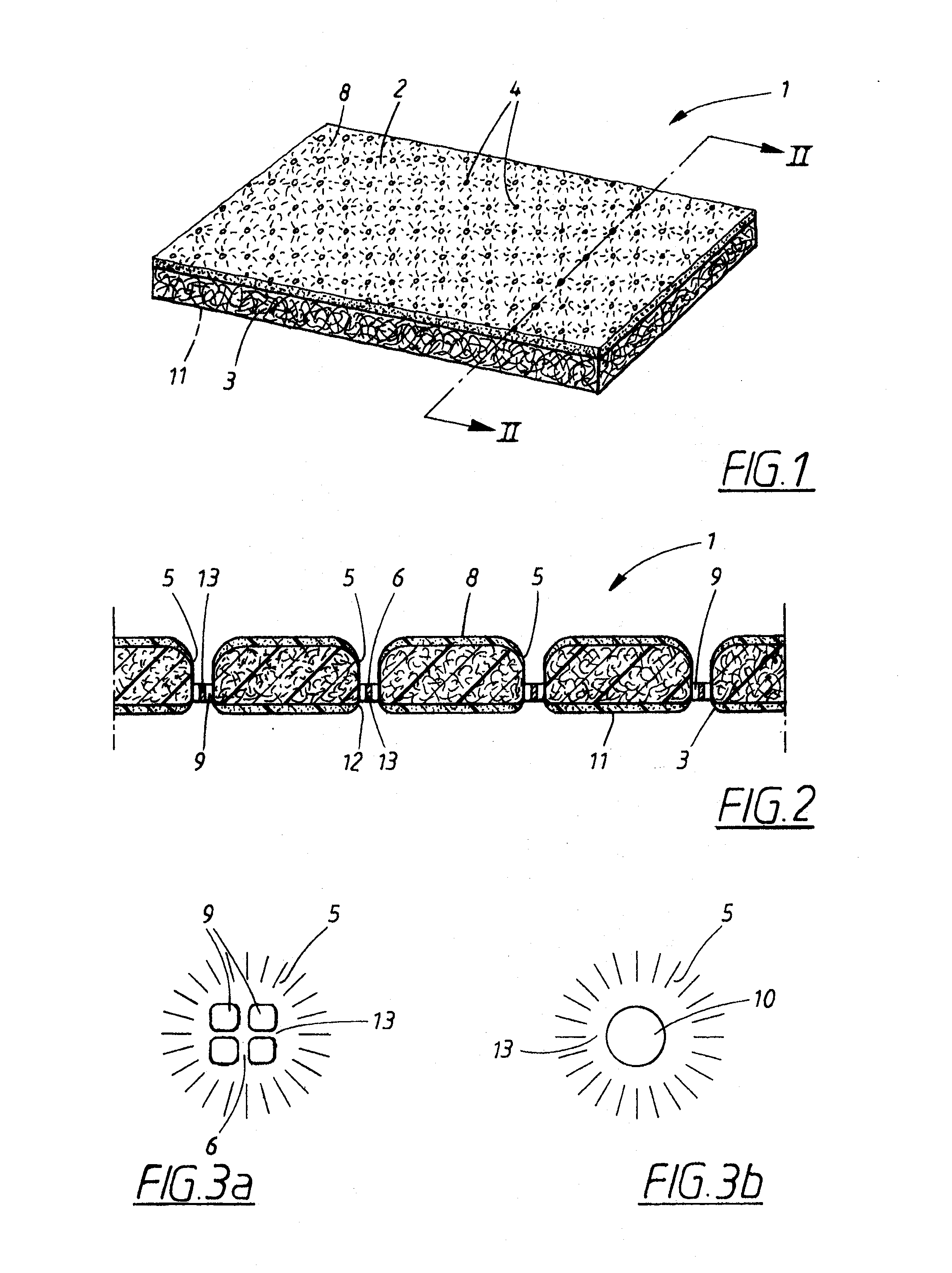
[0040]The term material web in the present invention denotes a web comprising one or several layers. For example, a material web can constitute, as described below, a surface layer and a liquid transfer layer in an absorbent article. In addition, a layer can comprise one or several strata.

[0041]The term film-like structure denotes a structure comprising melted or softened thermoplastic components. The film-like structure suitably comprises intact fibres, which are bonded together by the melted or softened thermoplastic components and give strength to the welded joints. However, it is also conceivable that all fibres in the film-like structure have been melted. The amount of intact fibres can vary greatly from case to case depending on, for example, which materials are included in the material web, how much energy is applied to the material web in the binding step and how much time the binding step takes.

[0042]FIG. 1 shows a material web in the form of a laminate 1 comprising a first...


PUM

PropertyMeasurementUnit
thicknessaaaaaaaaaa
pressureaaaaaaaaaa
diameteraaaaaaaaaa

Abstract

A material web includes at least one fibrous material layer and has a first and a second surface. The material web comprises recesses in the first surface, which recesses have a diminishing cross-sectional area along at least a part of their extension in a direction towards the second surface. The material web further comprises recesses in the second surface, which recesses have a diminishing cross-sectional area along at least a part of their extension in a direction towards the first surface, and which form pairs with opposite recesses in the first surface. The recesses in at least some of the pairs are connected to each other via at least one hole. A method for producing such a material web and an article comprising such a material web is also provided.

Description

TECHNICAL FIELD[0001]The present invention concerns a material web for use in an absorbent article, which material web comprises at least one fibrous material layer and has a longitudinal direction, a transverse direction and a thickness direction as well as a first and a second surface, which surfaces are situated on opposite sides of the material web and of which one surface is intended to face towards the user of the article while the opposite surface is intended to face away from the user of the article. The material web comprises recesses in the first surface with an extension in the thickness direction of the material web, which recesses have a diminishing cross-sectional area along at least a part of their extension in a direction towards the second surface. The present invention also concerns an absorbent article comprising such a material web and a method for producing such a material web.BACKGROUND ART[0002]Absorbent articles which are intended for single use usually compr...

Claims


Application Information

Patent Timeline
Patent Type & Authority Applications(United States)
IPC IPC(8): A61F13/45B32B7/02B32B3/24B32B3/30B29C65/08B32B38/04D04H1/54D04H1/544D04H1/549D04H1/55D04H1/555D04H1/559
CPCA61F13/512Y10T428/24281A61F13/51478A61F13/533A61F13/536A61F13/53708A61F13/53756A61F2013/15504A61F2013/53782B32B3/06B32B5/26D04H1/54D04H1/544D04H1/549D04H1/55D04H1/555D04H1/559A61F13/5146B32B5/022B32B3/30B32B2262/0253B32B2262/0261B32B2262/0276B32B2307/726B32B2307/734B32B2555/00
Inventor ANDERSSON, PATRIKPERSSON, ANDERS
Owner SCA HYGIENE PROD AB
Why Eureka
Try Eureka