
Irradiation angle adjuster for street light

a technology for street lights and adjusters, which is applied in fixed installations, lighting and heating devices, and support devices for lighting and heating, etc., and can solve problems such as unsatisfactory illumination effects

Inactive Publication Date: 2011-01-06
PARK YOUNG MIN
View PDF4 Cites 42 Cited by
  • Summary
  • Abstract
  • Description
  • Claims
  • Application Information

AI Technical Summary

Problems solved by technology

However, such a conventional street light is problematic in that the illumination effect may not be satisfactory depending on the circumference, such as an installation place or location, the grade of the ground, etc.

Method used


Image

  • Irradiation angle adjuster for street light
  • Irradiation angle adjuster for street light
  • Irradiation angle adjuster for street light

Examples


second embodiment

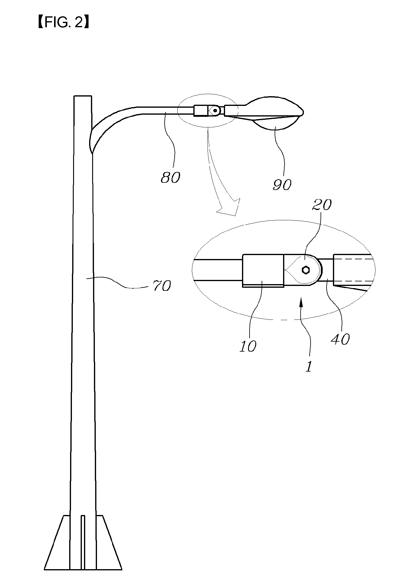
[0020]FIG. 2 is a side view of a street light provided with an irradiation angle adjuster according to a first embodiment of the present invention. FIG. 3 is a perspective view of the irradiation angle adjuster 1 according to the first embodiment of the present invention. FIG. 4 is an exploded perspective view of FIG. 3. FIG. 5 is a bottom perspective view of FIG. 4. FIG. 6 is of side sectional views showing the operation of the irradiation angle adjuster 1 according to the first embodiment of the present invention. FIG. 7 is a side section view of an irradiation angle adjuster for a street light, according to the present invention.

[0021]As shown in FIGS. 2 through 6, the irradiation angle adjuster 1 according to the first embodiment of the present invention includes an arm coupling part 10, a boss coupling part 20, a boss 30, a lamp mounting part 40 and a worm gear 50.

[0022]As shown in FIG. 2, the irradiation angle adjuster 1 is installed on a street light which has a typical struc...


PUM


Abstract

Disclosed herein is an irradiation angle adjuster for a street light which enables one to adjust an angle of light emitted from a lamp. The adjuster includes an arm coupling part, a boss coupling part, a boss, a lamp mounting part and a worm gear. The arm coupling part is coupled to the arm of the street light. The boss coupling part is provided on the arm coupling part. Coupling protrusions are provided at both sides on the boss coupling part. The boss is coupled between the coupling protrusions. Gear teeth are formed on the rear surface of the boss. The lamp mounting part is provided on the front surface of the boss. The lamp is mounted to the lamp mounting part. The worm gear is installed in the boss coupling part and engages with the gear teeth of the boss to transmit rotating force to the boss.

Description

CROSS REFERENCE TO RELATED APPLICATION[0001]This application claims the benefit of Korean Patent Application No. 20-2009-0008617, filed Jul. 3, 2009, entitled “Adjuster of irradiation angle for street light”, which is hereby incorporated by reference in its entirety into this application.BACKGROUND OF THE INVENTION[0002]1. Technical Field[0003]The present invention relates generally to irradiation angle adjusters for street lights and, more particularly, to an irradiation angle adjuster for a street light which is constructed such that an angle of light emitted from a lamp can be adjusted by rotating a worm gear.[0004]2. Description of the Related Art[0005]Generally, street lights are illumination apparatuses which are installed on the edges of a road for the sake of the safety and security of road traffic. Depending on an installation location (for example, an expressway, a general roadway, a sidewalk, a residential street, etc.), an appropriate kind of street light is used.[0006]A...

Claims


Application Information

Patent Timeline
Patent Type & Authority Applications(United States)
IPC IPC(8): F21V21/14
CPCF21V21/15F21V21/26F21S8/086Y02B20/72F21W2131/103F21S13/10F21V17/02
Inventor PARK, YOUNG MIN
Owner PARK YOUNG MIN
Learn More