
Variable frequency transformer having multiple horizontal rotary transformers with common controls and voltage infrastructure and method

a technology of variable frequency transformers and horizontal rotary transformers, which is applied in the direction of reciprocating combination engines, multiple dynamo-motor starters, dynamo-electric converter control, etc., can solve the problems of large transformer shafts, expensive infrastructure for supporting transformers, and large transformers

Active Publication Date: 2010-12-30
GENERAL ELECTRIC CO
View PDF17 Cites 9 Cited by
  • Summary
  • Abstract
  • Description
  • Claims
  • Application Information

AI Technical Summary

Benefits of technology

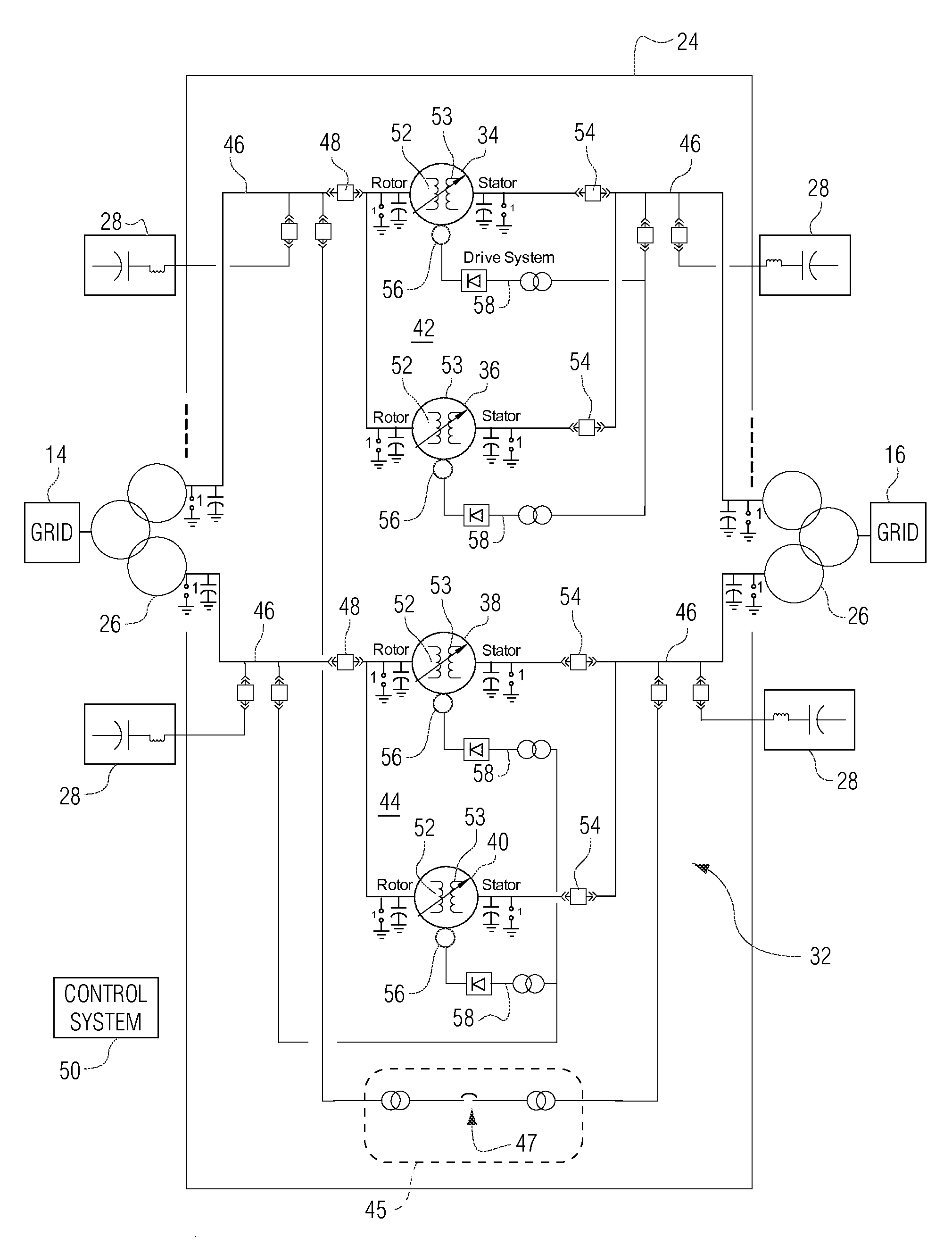
[0006]A variable frequency transformer asynchronous power transformer has been developed that includes multiple relatively small rotating machines, e.g., using large motor technology instead of hydro generator technology to create rotary transformers, which in combination convert AC power from one power grid to AC power compatible with another power grid. The multiple smaller rotating machines are connected in groups of parallel machines, and are commonly controlled to form a single variable frequency transformer.
[0007]A variable frequency transformer comprising: a plurality of rotary transformers each including a rotor winding, a stator winding and a drive motor; a first parallel circuit including at least two of the rotary transformers arranged in parallel and having an isolating circuit breaker connected to a first winding of each of the at least two of the rotary transformers in the first parallel circuit, wherein the first winding is the rotor winding or the stator winding, and a separate synchronizing circuit breaker connected to each of a second winding for each of the rotary transformers in the first parallel circuit, wherein the second winding is the rotor winding or the stator winding which is not the first winding; a second parallel circuit including at least two of the rotary transformers arranged in parallel and having an isolating circuit breaker connected to the first winding of each of the at least two of the rotary transformers in the second parallel circuit, and a separate synchronizing circuit breaker connected to each second winding for each of the rotary transformers in the second parallel circuit; a first main transformer having a first winding connectable to a first power grid and at least one secondary winding connectable to the isolating circuit breaker in the first parallel circuit and in the second parallel circuit; a second main transformer having a first winding connectable to a second power grid and at least one secondary winding connectable to each of the synchronizing circuit breakers in the first parallel circuit and in the sec

Problems solved by technology

The transformers are massive and the shafts for the transformers are extensive.
Conventional VFTs typically require expensive infrastructure to support the transformer and are housed in special tall buildings.
These substations are often remote and not easily accessible for construction of the VFT.
The construction costs for installing a VFT at a remote substation can be substantial.

Method used


Image

  • Variable frequency transformer having multiple horizontal rotary transformers with common controls and voltage infrastructure and method
  • Variable frequency transformer having multiple horizontal rotary transformers with common controls and voltage infrastructure and method
  • Variable frequency transformer having multiple horizontal rotary transformers with common controls and voltage infrastructure and method

Examples


Embodiment Construction

[0014]FIG. 1 is a diagram of a power substation 10 having a variable frequency transformer 12 to convert the power from one power grid 14 (shown in the figure as high voltage lines) coupled to the substation to another power grid 16 (shown has high voltage lines) coupled to the substation. The variable frequency transformer 12 comprises two or more pairs of rotating machines 18 (four rotary transformers are shown in FIG. 1).

[0015]These rotating machines 18 may include a rotor, stator and drive motor that are configured to operate as a transformer. The rotating machines may, for example, be a conventional industrial motor, such as a 25 mega-watt (MW) motor that may be conventionally used in a manufacturing plant or for marine ship propulsion. The rotor shaft of each of the rotating machines may be horizontal. The rotating machines may be mounted on one or more steel frames 20, 21 that are seated on a rectangular foundation 22 of a building 24 in the substation. Each frame 20, 21 may ...


PUM


Abstract

A variable frequency transformer including: a first parallel circuit including at least two of the rotary transformers arranged in parallel and having an isolating circuit breaker connected to a rotor winding of each of the rotary transformers, and a separate synchronizing circuit breaker connected to a stator winding in each of the rotary transformers in the first parallel circuit; a first main transformer having a first winding connectable to a first power grid and a secondary winding connectable to the isolating circuit breaker in the first parallel circuit; a second main transformer having a first winding connectable to a second power grid and a secondary winding connectable to each of the synchronizing circuit breakers in the first parallel circuit, and a control system operatively connected to each of the synchronizing circuit breakers, the isolating circuit breakers and the drive motors for each of the rotary transformers.

Description

BACKGROUND OF THE INVENTION[0001]The invention relates to variable frequency transformers (VFTS) and, particularly, to the arrangement of rotary transformers, controls and infrastructure in VFTs.[0002]Variable frequency transformers are conventionally used to connect one power grid to another power grid. The two power grids carry alternating electrical current (AC) at potentially different frequencies, phases and voltages. A VFT provides a controlled alternating current (AC) path between two power grids. A VFT converts the AC power from one power grid to a frequency, phase and voltage that is suitable for the AC power in the other power grid.[0003]A variable frequency transformer is a continuously phase shifting transformer that operates at an adjustable phase angle. The VFT may be a bi-directional current transmission device that converts AC current from a first power grid for a second power grid, and vice versa. A VFT typically includes a rotary transformer with three-phase windin...

Claims


Application Information

Patent Timeline
IPC IPC(8): H02M5/16
CPCH02M5/32H02J3/08
Inventor MARKEN, PAUL E.
Owner GENERAL ELECTRIC CO
Learn More