
Liquid crystal display and method of manufacturing the same

a liquid crystal display and liquid crystal technology, applied in semiconductor devices, instruments, computing, etc., can solve the problems of deterioration of the display quality of the lcd, the inability of the reflective lcd to display an image, and the inability to effectively prevent the electro-optical characteristic of the liquid crystal layer, so as to improve the display quality the manufacturing process of the liquid crystal display is simplified, and the effect of preventing the effect of electro-optical characteristi

Active Publication Date: 2010-12-30
SAMSUNG DISPLAY CO LTD
View PDF9 Cites 23 Cited by
  • Summary
  • Abstract
  • Description
  • Claims
  • Application Information

AI Technical Summary

Benefits of technology

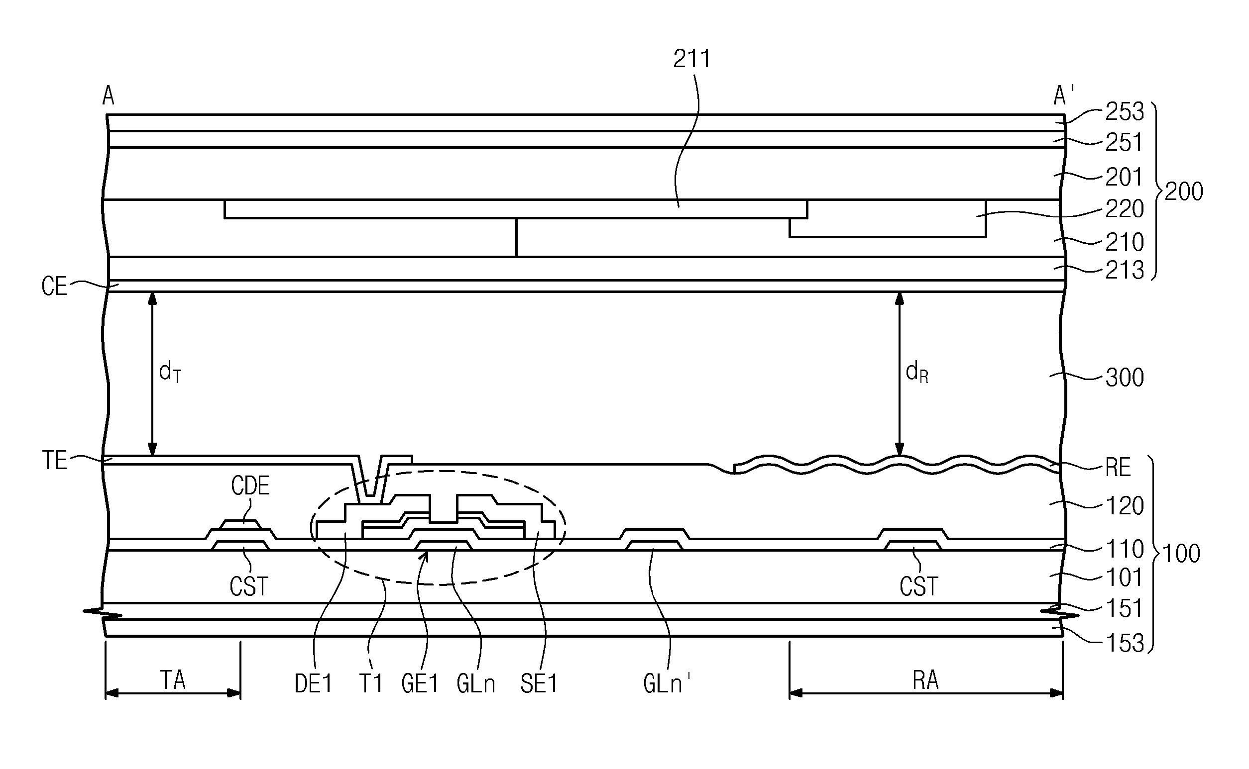
The present invention provides a transflective liquid crystal display with a single cell gap structure and improved display quality. The display includes pixels with a transmissive area and a reflective area, and a voltage controller that controls the voltage of the pixels. The voltage controller includes a thin film transistor, a charge dividing electrode, and a storage line that overlaps with the charge dividing electrode to form a capacitor that controls the voltage of the pixels. The reflective area has a smaller cell gap than the transmissive area. The second substrate may include a color filter layer and a transparent organic layer with a different thickness in different areas. The display also includes a first polarizer and a second polarizer, and at least one phase retardation film between the first and second substrates. The method of manufacturing the display includes forming a first substrate with thin film transistors, a transmissive pixel electrode, and a reflective pixel electrode, and forming a voltage controller overlapping at least a portion of the transmissive pixel electrode. The technical effects of the invention include improved display quality, reduced power consumption, and improved manufacturing process.

Problems solved by technology

Compared to the reflective LCD, the transmissive LCD, which requires the backlight unit, has a high power consumption.
Although it does not require a backlight, and thus consumes less power, the reflective LCD cannot display an image if there is insufficient ambient light.
However, the transflective LCD typically has a single cell gap structure and, as a result, a gray-scale difference occurs in the reflective and transmissive areas due to a phase retardation difference therein, thereby causing deterioration of display quality of the LCD.
As a result, it is difficult to control a liquid crystal director, due to the step difference, and defects in patterning occur in a manufacturing process, thereby causing deterioration of both the display quality and production efficiency of the LCD.

Method used


Image

  • Liquid crystal display and method of manufacturing the same
  • Liquid crystal display and method of manufacturing the same
  • Liquid crystal display and method of manufacturing the same

Examples


Embodiment Construction

[0065]The invention now will be described more fully hereinafter with reference to the accompanying drawings, in which various embodiments are shown. This invention may, however, be embodied in many different forms, and should not be construed as limited to the embodiments set forth herein. Rather, these embodiments are provided so that this disclosure will be thorough and complete, and will fully convey the scope of the invention to those skilled in the art. Like reference numerals refer to like elements throughout.

[0066]It will be understood that when an element is referred to as being “on” another element, it can be directly on the other element or intervening elements may be present therebetween. In contrast, when an element is referred to as being “directly on” another element, there are no intervening elements present. As used herein, the term “and / or” includes any and all combinations of one or more of the associated listed items.

[0067]It will be understood that, although the...


PUM

PropertyMeasurementUnit
contact angleaaaaaaaaaa
distanceaaaaaaaaaa
diameteraaaaaaaaaa

Abstract

A liquid crystal display includes a first substrate including pixels, each having a transmissive area and a reflective area, a second substrate, and a liquid crystal layer disposed between the first and second substrates. Each of the pixels includes first and second thin film transistors which output a data signal in response to a first gate signal, a transmissive pixel electrode disposed in the transmissive area and electrically connected to the first thin film transistor to charge a first pixel voltage based on the data signal, a reflective pixel electrode disposed in the reflective area and electrically connected to the second thin film transistor to charge a second pixel voltage based on the data signal, and a voltage controller which controls the first pixel voltage and the second pixel voltage in response to a second gate signal, which is generated after the first gate signal.

Description

[0001]This is a U.S. non-provisional patent application claims priority under 35 U.S.C. §119 of Korean Patent Application No. 10-2010-0028236 filed on Mar. 30, 2010, and is a Continuation-in-Part of application Ser. No. 12 / 620,801 filed on Nov. 18, 2009 which claims priority to Korean Patent Application No. 10-2009-0059233, filed on Jun. 30, 2009, all of which are incorporated by reference as if set forth fully herein.BACKGROUND OF THE INVENTION[0002]1. Field of the Invention[0003]The present invention relates to a liquid crystal display and a method of manufacturing the liquid crystal display. More particularly, the present invention relates to a transflective liquid crystal display having a single cell gap and a method of manufacturing the liquid crystal display.[0004]2. Description of the Related Art[0005]A liquid crystal display (“LCD”) typically includes a liquid crystal layer disposed between two transparent substrates. To display a desired image, the LCD drives the liquid cry...

Claims


Application Information

Patent Timeline
Patent Type & Authority Applications(United States)
IPC IPC(8): G09G5/00G02F1/1335H01L21/28
CPCG02F1/133555G02F1/133707G02F1/1362G09G3/3659G02F1/1368G09G2300/0842G02F1/133528G02F1/136286G09G2300/0456
Inventor JEONG, YOUN HAKYEOM, JOOSEOKOH, KEUNCHANUM, YOONSUNGLEE, HEEHWANRYU, KYUWANLYU, JAEJINPARK, MYUNGJAE
Owner SAMSUNG DISPLAY CO LTD
Learn More