
Vacuum blood collection tube

a vacuum blood collection and vacuum technology, applied in the field of vacuum blood collection tubes, can solve the problems of dna damage, dna extraction efficiency decline, blood sample collected in vacuum blood collection tubes not being preserved as whole blood for a long period of several days, etc., and achieve the effect of reducing pressure state and less susceptible to low temperature fractur

Inactive Publication Date: 2010-12-23
KANEKA CORP
View PDF13 Cites 18 Cited by
  • Summary
  • Abstract
  • Description
  • Claims
  • Application Information

AI Technical Summary

Benefits of technology

[0009]One aspect of the present invention is a vacuum blood collection tube. This vacuum blood collection tube comprises a bottomed tube composed of a low temperature resistant material that is less susceptible to low temperature fracture when cryopreserved at an ultra-low temperature of −40° C. to −200° C., and having a bottom portion at one end and an opening at the other end; a stopper attached to the opening of the bottomed tube before blood collection, being in close contact with the opening of the bottomed tube so that the reduced pressure state inside the bottomed tube can be maintained, and having a needle piercing portion composed of a rubber material that can be pierced with a blood collection needle; and a cryopreservation cap composed of the low temperature resistant material, attached to the opening of the bottomed tube after blood collection, and sealing the opening of the bottomed tube under the condition of the ultra-low temperature so that the liquid tight state of the bottomed tube can be maintained.

Problems solved by technology

Therefore, so far, the blood sample collected in the vacuum blood collection tube has not been preserved as whole blood for a long period of several days or more.
Also, when a blood sample once frozen is thawed again, DNA damage occurs, and DNA extraction efficiency decreases.
However, in the conventional vacuum blood collection tube, a plastic material, such as PET, is often used, as the material of the vacuum blood collection tube, and a material that can endure storage at ultra-low temperature is not used.
Therefore, when it is attempted to cryopreserve the conventional vacuum blood collection tube as it is, low temperature fracture may occur when the conventional vacuum blood collection tube is immersed in liquid nitrogen.
But, different materials are often used for the bottomed tube, the stopper, and the lid, and when these are held at ultra-low temperature, a clearance may be produced between the stopper or the lid and the bottomed tube due to difference in the degree of thermal shrinkage.
In such a case, from the clearance, external liquid nitrogen and the like may enter the vacuum blood collection tube, and the sample inside the vacuum blood collection tube may leak to the outside.
However, the operation of transferring the blood sample from the vacuum blood collection tube to the blood storage container not only requires labor for the operation itself, but also may cause the blood spilled or scattered during the operation.
Therefore, effort and burden on the operator of the transferring operation are very large.

Method used


Image

  • Vacuum blood collection tube
  • Vacuum blood collection tube
  • Vacuum blood collection tube

Examples


first embodiment

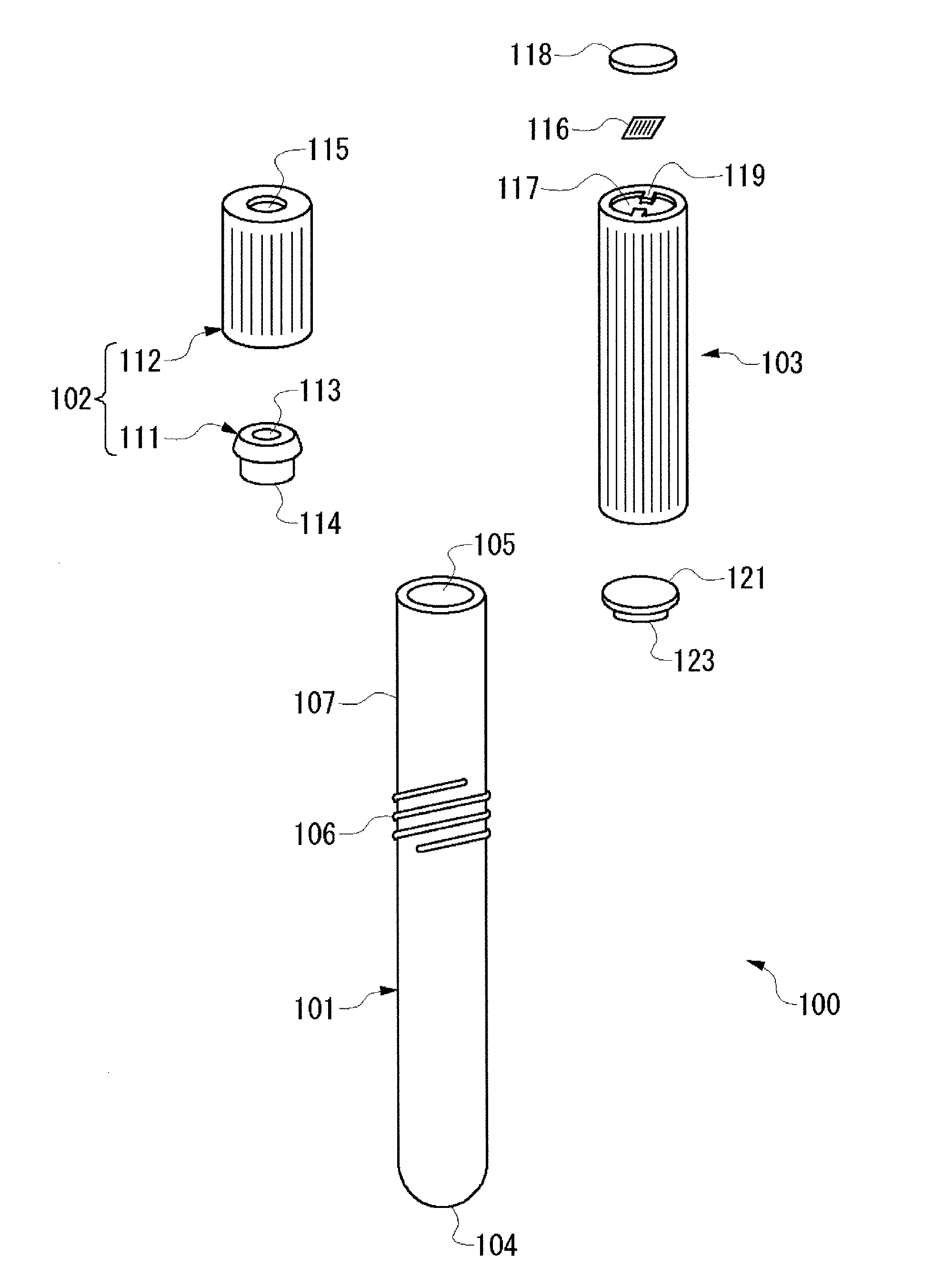
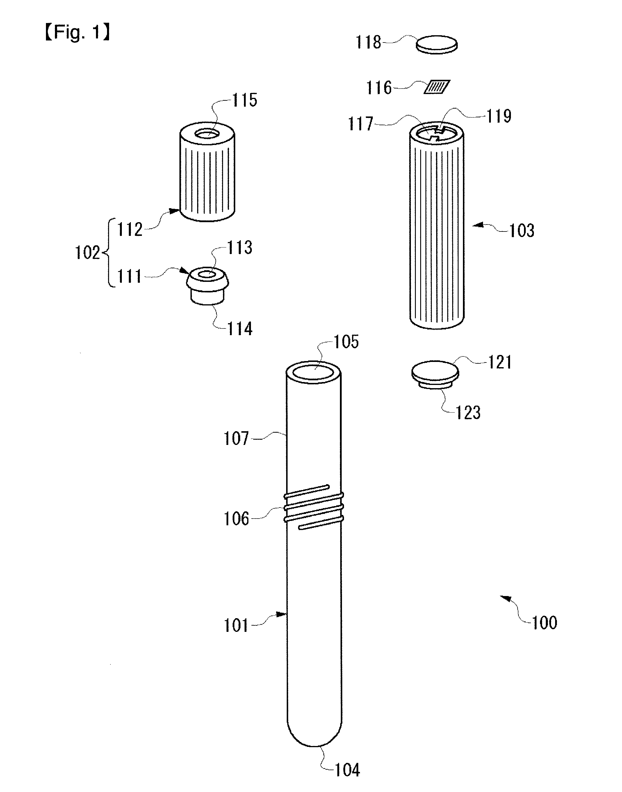
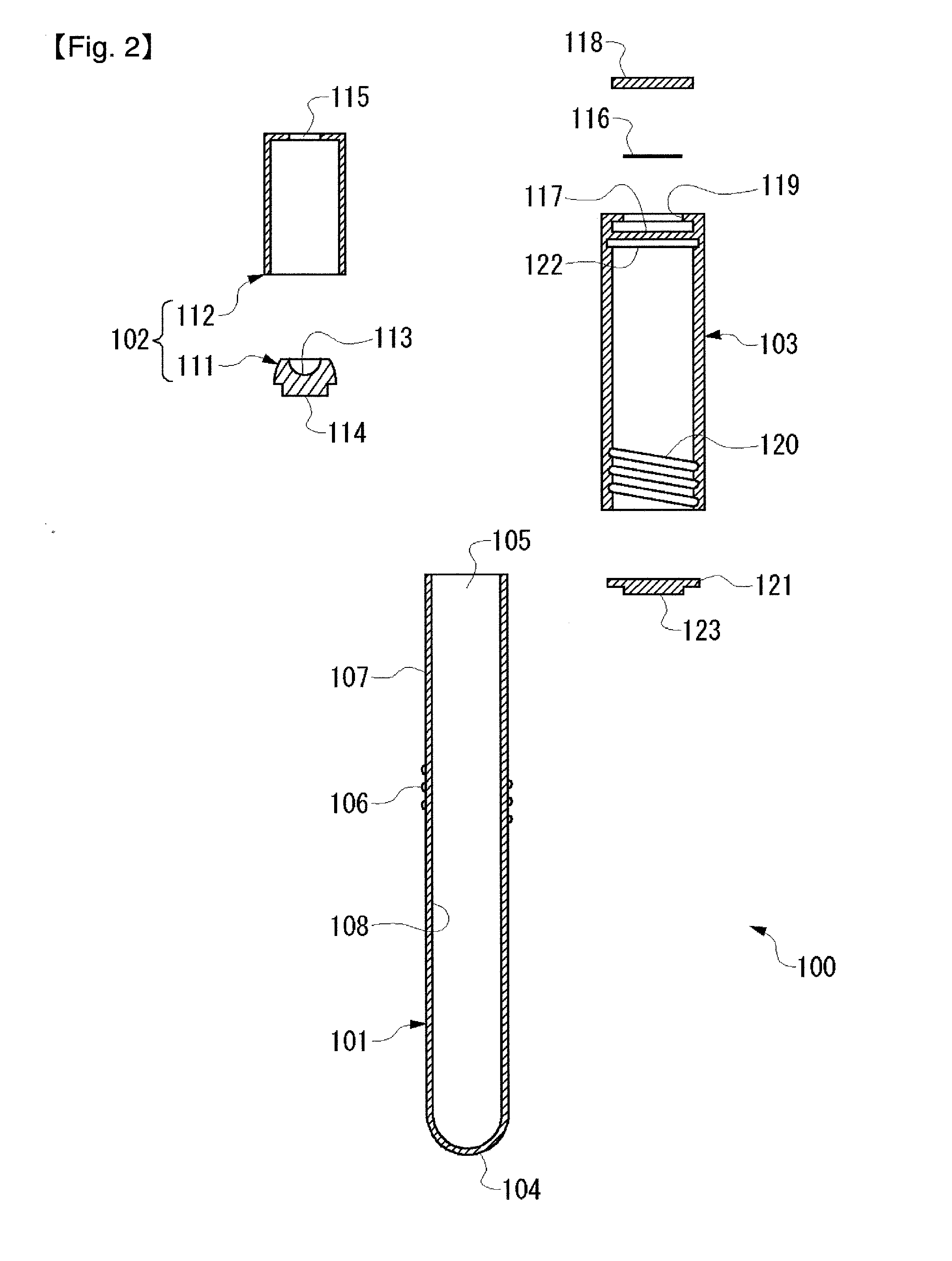
[0099]A vacuum blood collection tube in the first embodiment of the present invention is shown in FIG. 1 to FIG. 7. FIG. 1 is a perspective view showing the configuration of the vacuum blood collection tube, and FIG. 2 is a cross-sectional view showing the configuration of the vacuum blood collection tube. As shown in FIG. 1 and FIG. 2, a vacuum blood collection tube 100 comprises a bottomed tube 101, a stopper 102, and a cryopreservation cap 103. In the vacuum blood collection tube 100 in this embodiment, the cryopreservation cap 103 is attached to the bottomed tube 101, in exchange of the stopper 102.

[0100]The bottomed tube 101 is generally cylindrical and has a bottom portion 104 at one end and an opening 105 at the other end. A thread portion 106 is provided on the outer peripheral surface of the bottomed tube 101. This thread portion 106 is provided on the surface of the bottomed tube 101 and corresponds to the tube side thread portion of the present invention.

[0101]The above t...

second embodiment

[0141]Next, a vacuum blood collection tube in the second embodiment of the present invention will be described using FIG. 8 to FIG. 15. Here, description is given focusing on points where the vacuum blood collection tube in this embodiment is different from that in the first embodiment. Therefore, unless otherwise specified here, the configuration of this embodiment is similar to that of the first embodiment.

[0142]FIG. 8 is a perspective view showing the configuration of the vacuum blood collection tube, and FIG. 9 is a cross-sectional view showing the configuration of the vacuum blood collection tube. As shown in FIG. 8 and FIG. 9, a vacuum blood collection tube 200 comprises a bottomed tube 201, a stopper 202, and a cryopreservation cap 203. In the vacuum blood collection tube 200 in this embodiment, the cryopreservation cap 203 is attached to the bottomed tube 201 over the stopper 202 (covering the stopper 202).

[0143]The bottomed tube 201 is generally cylindrical and has a bottom...

third embodiment

[0164]Next, a vacuum blood collection tube in the third embodiment of the present invention will be described using FIG. 16 and FIG. 17. Here, description is given focusing on points where the vacuum blood collection tube in this embodiment is different from that in the first embodiment. Therefore, unless otherwise specified here, the configuration of this embodiment is similar to that of the first embodiment.

[0165]FIG. 16 is a plan view showing a vacuum blood collection tube set. As shown in FIG. 16, in this embodiment, a bottomed tube 301 to which a stopper 302 is attached, and a cryopreservation cap 303 are connected by a connection part 324. In this case, it can also be said that the bottomed tube 301 to which the stopper 302 is attached, and the cryopreservation cap 303 constitute a vacuum blood collection tube 300 set (also referred to as a vacuum blood collection tube set) with the connection part 324.

[0166]FIG. 17 is a perspective view showing one example of the connection p...


PUM

PropertyMeasurementUnit
Temperatureaaaaaaaaaa
Thicknessaaaaaaaaaa

Abstract

A vacuum blood collection tube (100) comprises a bottomed tube (101) composed of a low temperature resistant material that is less susceptible to low temperature fracture when cryopreserved at ultra-low temperature, a stopper (102) having a needle piercing portion (113) composed of a rubber material that can be pierced with a blood collection needle (110), and a cryopreservation cap (103) composed of the low temperature resistant material. Before blood collection, the stopper (102) is attached to the bottomed tube (101) to maintain the reduced pressure state inside the bottomed tube (101). Thus, blood collection by a vacuum blood collection method is possible. After blood collection, the cryopreservation cap (103) is attached to the bottomed tube (101), so that the liquid tight state of the bottomed tube (101) is maintained, and cryopreservation at ultra-low temperature as it is possible. Thus, the collected blood sample can be cryopreserved at ultra-low temperature as it is, without being transferred to another blood storage container, so that effort and burden on an operator can be significantly reduced.

Description

TECHNICAL FIELD[0001]The present invention relates to a vacuum blood collection tube in which a collected blood sample can be cryopreserved as it is.[0002]A vacuum blood collection tube is widely used in biochemical tests, blood sugar measurement, erythrocyte sedimentation rate tests, blood coagulation measurement, serological tests, and hematological tests because of its easy operation for blood collection. Conventionally, as the vacuum blood collection tube, one in which a rubber stopper that can be pierced with a blood collection needle is attached to a bottomed tube having an opening has been known. For example, such a vacuum blood collection tube is disclosed in Japanese Patent Laid-Open No. 2005-253538 (pages 6 to 10, FIG. 1) and Japanese Patent Laid-Open No. 2005-261965 (pages 6 to 8, FIG. 1). In a conventional vacuum blood collection tube, before blood collection, the stopper is attached to the opening of the bottomed tube, and the stopper is in close contact with the openin...

Claims


Application Information

Patent Timeline
IPC IPC(8): C12M1/00B29C45/17
CPCA61B5/1438B01L3/50825B01L2200/0689G01N1/42B01L2300/042B01L2300/043B01L2300/044B01L2300/021A61B5/15003A61B5/150259A61B5/150351A61B5/150389A61B5/150473A61B5/150755A61B5/150786A61B5/154
Inventor NAKAE, HIROKIUESAKA, HARUKAMINEKAWA, ATSUHIKOKURONO, TAKESHI
Owner KANEKA CORP
Learn More