
Vehicular Rearview Mirror Elements and Assemblies Incorporating These Elements

a technology of rearview mirror and elements, applied in the field of electro-optical devices and equipment, can solve the problem of limited effective field of view of elements

Inactive Publication Date: 2010-12-23
GENTEX CORP
View PDF5 Cites 212 Cited by
  • Summary
  • Abstract
  • Description
  • Claims
  • Application Information

AI Technical Summary

Benefits of technology

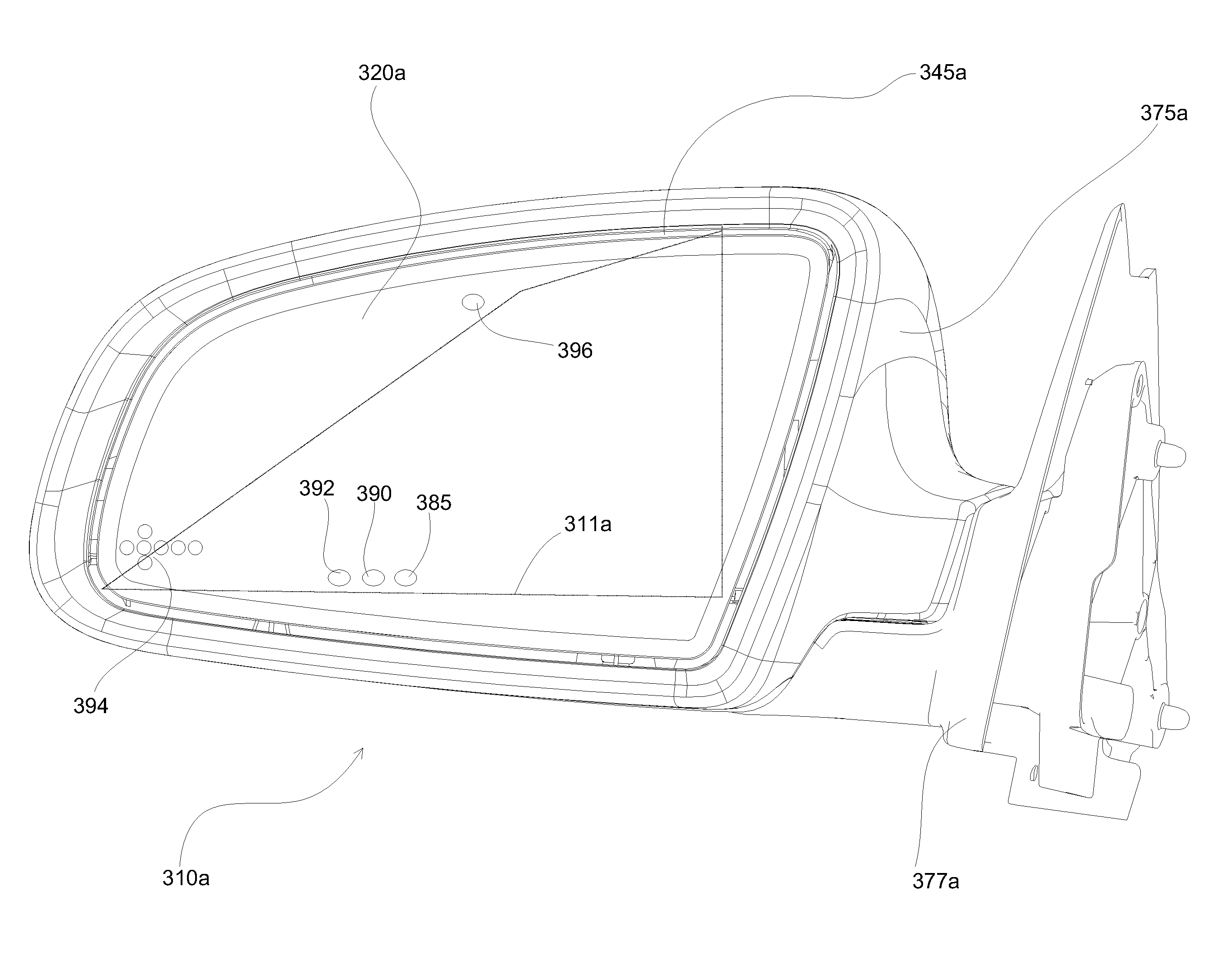
[0007]At least one embodiment of the present invention provides improved electro-optic mirror elements. A related embodiment has an effective field of view area substantially equal to the field of view associated with an area defined by the perimeter of the element....

Problems solved by technology

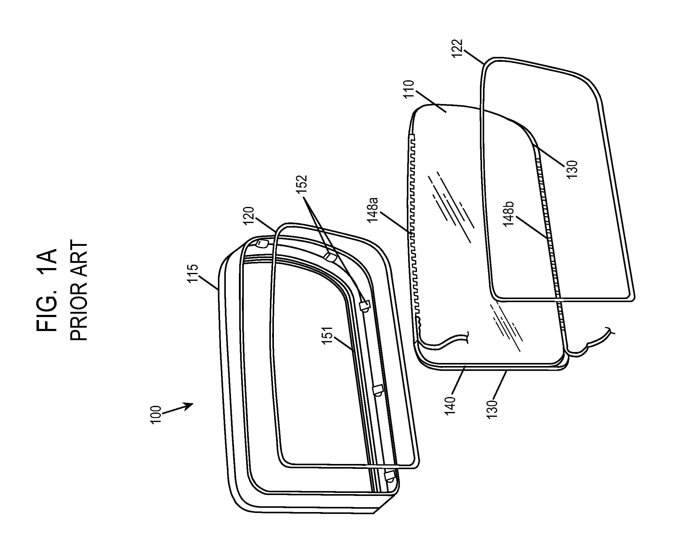
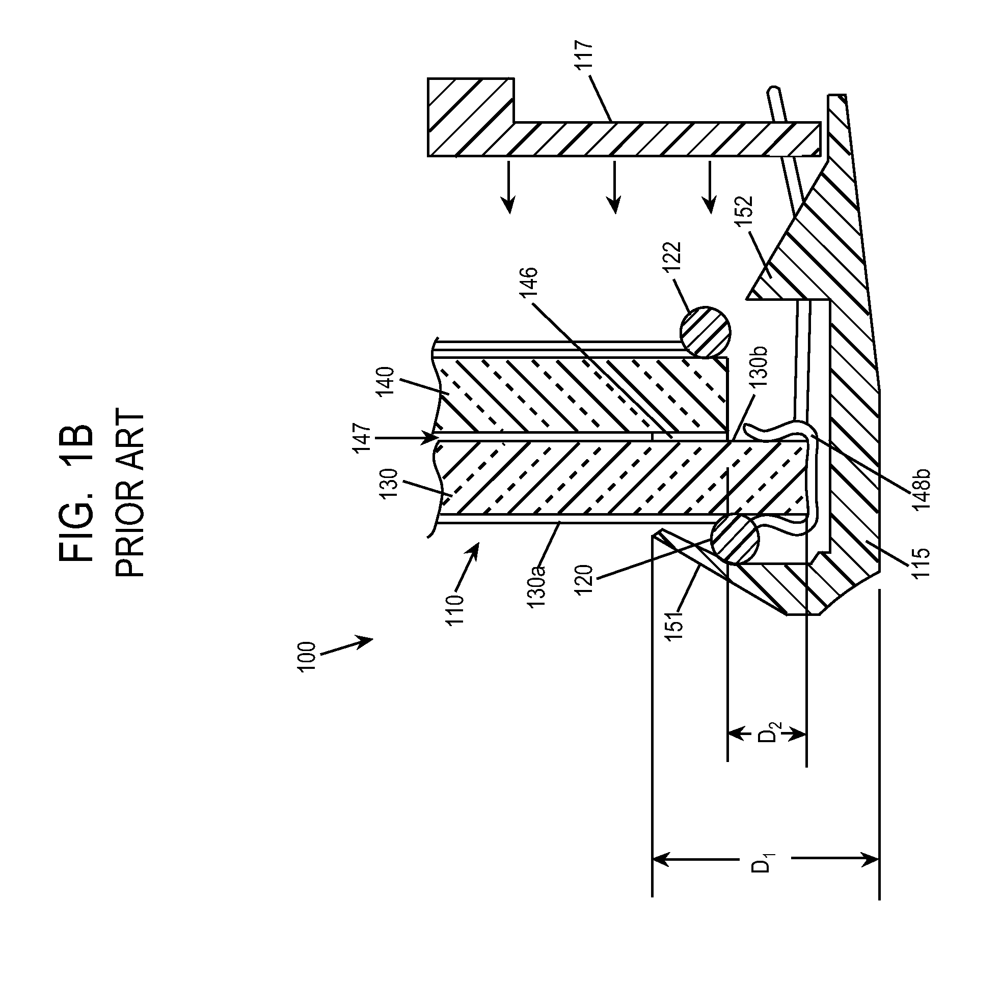
Often, the effective field of view of the element is limited, at least in part, by the construction of the element itself and / or an associated bezel.
While the above-described structure is readily manufacturable, styling concerns have arisen with respect to the width of the front lip of the bezel of an electrochromic mirror subassembly.

Method used


Image

  • Vehicular Rearview Mirror Elements and Assemblies Incorporating These Elements
  • Vehicular Rearview Mirror Elements and Assemblies Incorporating These Elements
  • Vehicular Rearview Mirror Elements and Assemblies Incorporating These Elements

Examples


example 2

Primary Seal Material

[0230]Using the thermal cure epoxy of Example 1 with 140 um glass beads caused a very heavy dimple pattern to be visible.

example 3

Primary Seal Material

[0231]Using the thermal cure epoxy of Example 1 with plastic beads (Techpolymer, Grade XX-264-Z, 180 um mean particle size, Sekisui Plastics Co. Ltd., Tokyo, Japan) caused no dimple pattern to be visible.

example 4

Primary Seal Material

[0232]Using the thermal cure epoxy of Example 1 with plastic fibers (Trilene, 140 um diameter monofilament line cut to 450 um lengths, Berkley, Spring Lake, Iowa) caused no dimple pattern to be visible.


PUM


Abstract

The present invention relates to improved electro-optic rearview mirror elements and assemblies incorporating the same. Area of the effective field of view of the electro-optic mirror element substantially equals to that defined by the outermost perimeter of the element.

Description

CROSS REFERENCE TO RELATED APPLICATIONS[0001]The present application is a continuation-in-part of U.S. patent application Ser. No. 12 / 750,357 filed on Mar. 30, 2010, which is a continuation of U.S. patent application Ser. No. 12 / 154,736, filed on May 27, 2008, which is a continuation of U.S. patent application Ser. No. 11 / 477,312 filed on Jun. 29, 2006 and now issued as U.S. Pat. No. 7,379,225, which is a continuation of U.S. patent application Ser. No. 11 / 066,903 filed on Feb. 25, 2005 and now issued as U.S. Pat. No. 7,372,611, which in turn claims priority under 35 U.S.C. §119 to U.S. Provisional Application Ser. Nos. 60 / 548,472 filed on Feb. 27, 2004, and 60 / 605,111 filed on Aug. 27, 2004, and 60 / 614,150 filed on Sep. 29, 2004. The U.S. patent application Ser. No. 11 / 066,903 is also a continuation-in-part of U.S. patent application Ser. Nos. 10 / 260,741 filed Sep. 30, 2002 and now issued as U.S. Pat. Nos. 7,064,882 and 10 / 430,885 filed on May 6, 2003 and now issued as U.S. Pat. No...

Claims


Application Information

Patent Timeline
IPC IPC(8): B60R1/12G02F1/157
CPCB60R1/088G02F1/163G02F1/161G02F1/1533
Inventor BUGNO, MARK D.TONAR, WILLIAM L.NEUMAN, GEORGE A.MINIKEY, JR., DANNY L.ANDERSON, JOHN S.
Owner GENTEX CORP
Learn More