
Apparatus and Method for Isolation from and Support of a Carbon Filtration System from an Ion Exchange System

a carbon filtration and carbon ion exchange technology, applied in the field of water treatment systems, can solve the problems of high total dissolved solids (tds), high ratio of drain water to product water, and inability to meet nsf requirements, etc., to eliminate undesirable tds spikes and high tds.

Inactive Publication Date: 2010-12-23
ECOWATER SYST
View PDF9 Cites 0 Cited by
  • Summary
  • Abstract
  • Description
  • Claims
  • Application Information

AI Technical Summary

Benefits of technology

The present invention provides a means to isolate or decouple the carbon tank from the rest of the system during the ion exchange regeneration cycle or specific parts of the regeneration cycle such that the carbon bed is bypassed and no water that contains brine, and is therefore high in TDS, enters the carbon tank. This eliminates the undesirable TDS spike and the need to flush the TDS spike out of the carbon. The invention also allows for independent optimization of the ion exchange regeneration backwash and the carbon backwash functions, and the frequency and duration of backwashing the carbon bed can be as required without having to occur with each regeneration backwash. The invention includes the use of a motorized ball valve, spool valve, or check valve in the flow path from the carbon tank to the ion exchange tank.

Problems solved by technology

The result of not flushing the brine from the carbon is that the initial product water delivered from the system will be high in total dissolved solids (TDS) which is both undesirable to the user and does not meet the National Sanitation Foundation (NSF) certification requirements for the minimum level of chlorides released from the system upon the completion of regeneration.
In addition, if an amount of water sufficient enough to flush the TDS out of the system is used, the ratio of drain water to product water is higher than desirable and further does not meet requirements for NSF certification.

Method used


Image

  • Apparatus and Method for Isolation from and Support of a Carbon Filtration System from an Ion Exchange System
  • Apparatus and Method for Isolation from and Support of a Carbon Filtration System from an Ion Exchange System
  • Apparatus and Method for Isolation from and Support of a Carbon Filtration System from an Ion Exchange System

Examples


Embodiment Construction

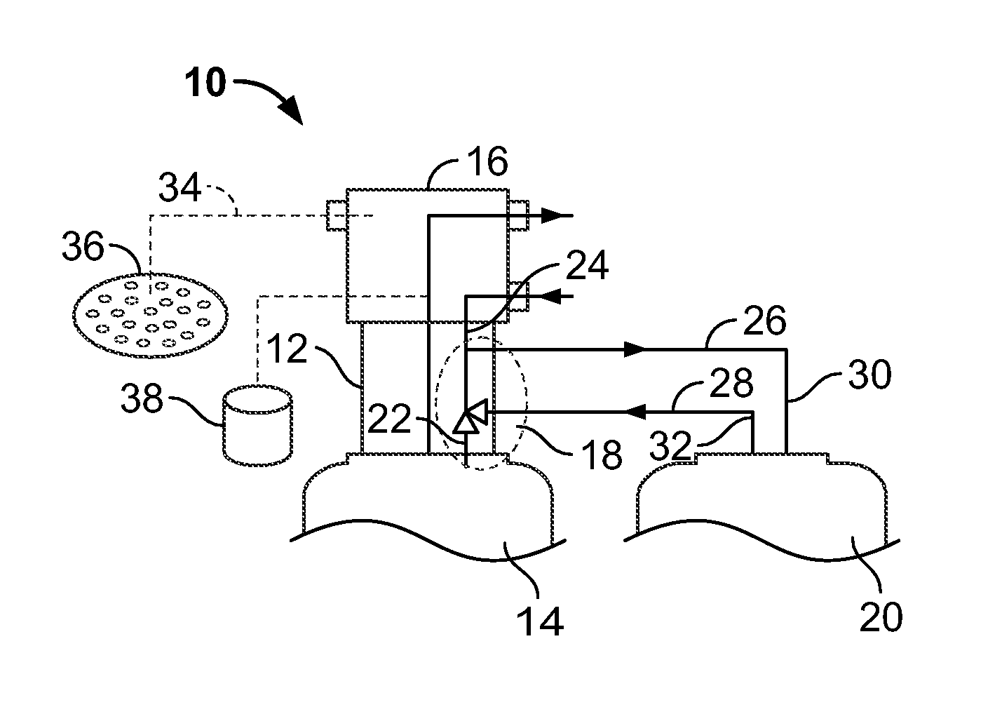
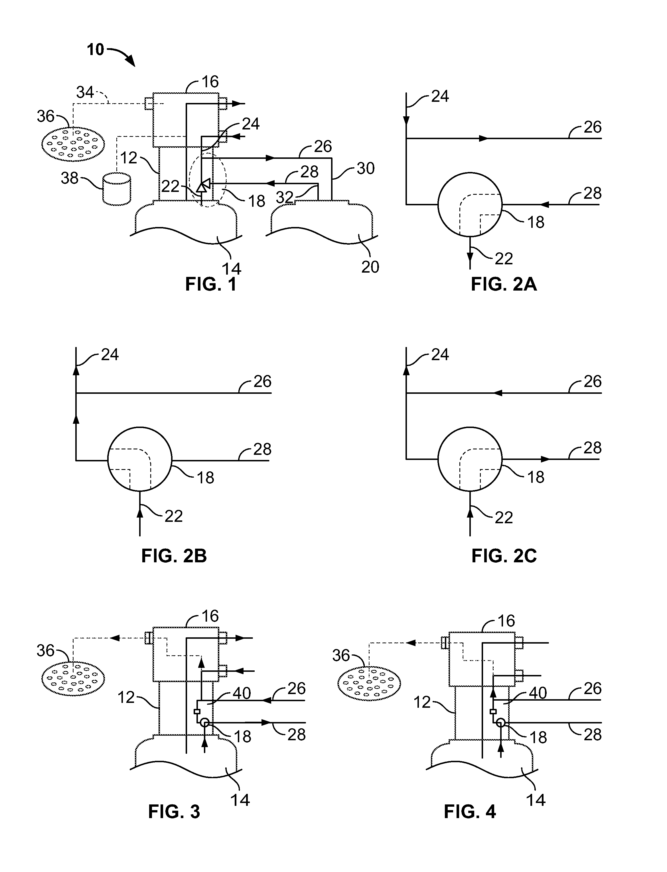
[0020]FIG. 1 is a schematic view of a system 10 with a valve adapter 12 depicted in accordance with the present invention. In particular, an ion exchange tank 14 is shown with an adapter 12 and valve rotor assembly 16. The valve 18 of the present invention is located in the adapter 12. The valve 18 may be a solenoid or motorized valve, under the same control as the valve rotor assembly 16. The embodiment of FIG. 1 is shown as providing a carbon filtration tank 20 followed by an ion exchange tank 14. However, the present invention may be adapted to a system having an ion exchange tank 14 followed by a carbon filtration tank 20.

[0021]FIG. 1 shows a schematic for a lower radial port 22, an upper radial port 24, a service outlet 26, a service inlet 28, a service inlet 30, and a service outlet 32. A drain line 34 is shown coupled to a drain 36. A brine valve 38 is shown coupled to the rotor assembly 16.

[0022]FIGS. 2A, 2B, and 2C are schematics which depict a motorized ball valve embodime...


PUM

PropertyMeasurementUnit
timeaaaaaaaaaa
hardnessaaaaaaaaaa
volumeaaaaaaaaaa

Abstract

A combination filtration and ion exchange system is provided. In one embodiment, the system includes a valve rotor, a carbon treatment tank, an ion exchange treatment tank and a valve. The valve rotor having a source water inlet, a service water outlet, a water treatment outlet, a water treatment inlet and a drain outlet. The carbon treatment tank having a service inlet and a service outlet, the service inlet coupled to the water treatment outlet. The ion exchange treatment tank having a service inlet and a service outlet, and the service outlet is coupled to the water treatment inlet. The valve having a carbon tank port, an ion exchange port, and a water treatment outlet, and a valve member having a first position and a second position, wherein in the first position, the service inlet of the ion exchange treatment tank is in fluid communication with the service outlet of the carbon treatment tank, and in the second position, the service inlet of the of the ion exchange treatment tank is in fluid communication with the water treatment outlet.

Description

TECHNICAL FIELD[0001]The present invention relates to water treatment systems and particularly to water treatment systems having a carbon treatment stage and an ion exchange stage, wherein the carbon filtration system may be isolated from and supported by the ion exchange system.BACKGROUND OF THE INVENTION[0002]It is known to provide a water treatment system in which carbon and ion exchange stages are connected in series, wherein water flows through one media followed by the other. The carbon tank provides removal of chlorine and the ion resin tank removes hardness. When the ion exchange resin needs to be regenerated, brine is introduced into the system, including the carbon bed. The brine is then flushed from the system to drain.[0003]Once the brine solution has been introduced into the carbon bed either before or after going through the ion exchange resin, a large volume of water is required to sufficiently flush the brine from the carbon. The result of not flushing the brine from...

Claims


Application Information

Patent Timeline
Patent Type & Authority Applications(United States)
IPC IPC(8): C02F9/02C02F1/42C02F1/28B01D15/00B01D15/18B01D15/20
CPCB01J20/20B01J49/00C02F1/008C02F2303/16C02F1/42C02F2209/001C02F2209/40C02F1/283
Inventor BARDWELL, DAVID T.HAEHN, STEVEN J.
Owner ECOWATER SYST
Learn More