
System and Apparatus for Determining Temperatures in a Fluid Analyte System

a fluid analyte and temperature technology, applied in the field of fluid analyte systems, can solve the problems of system slow response to environmental changes, inaccurate blood glucose concentration calculation, and inability to accurately measure blood glucos

Active Publication Date: 2010-12-23
ASCENSIA DIABETES CARE HLDG AG
View PDF80 Cites 62 Cited by
  • Summary
  • Abstract
  • Description
  • Claims
  • Application Information

AI Technical Summary

Benefits of technology

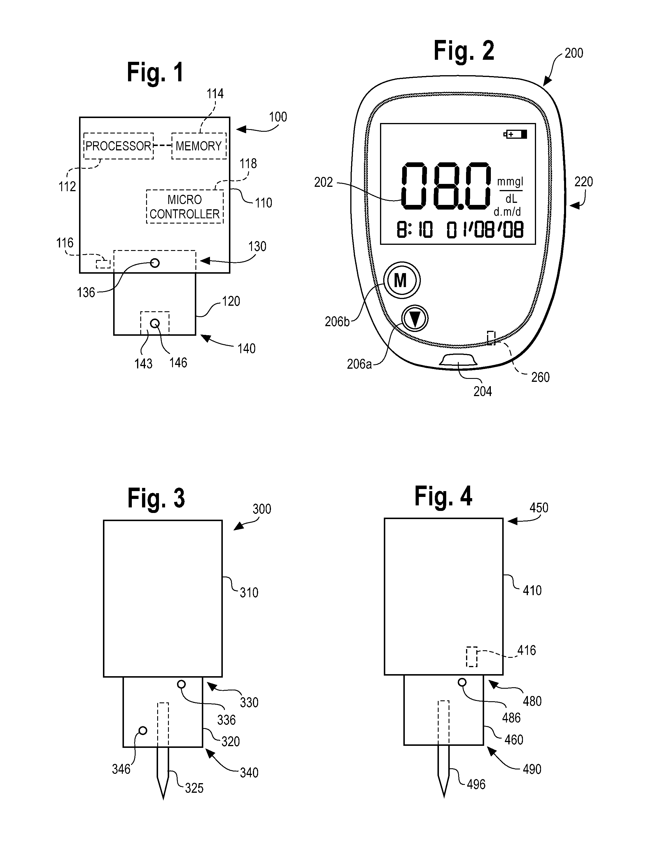
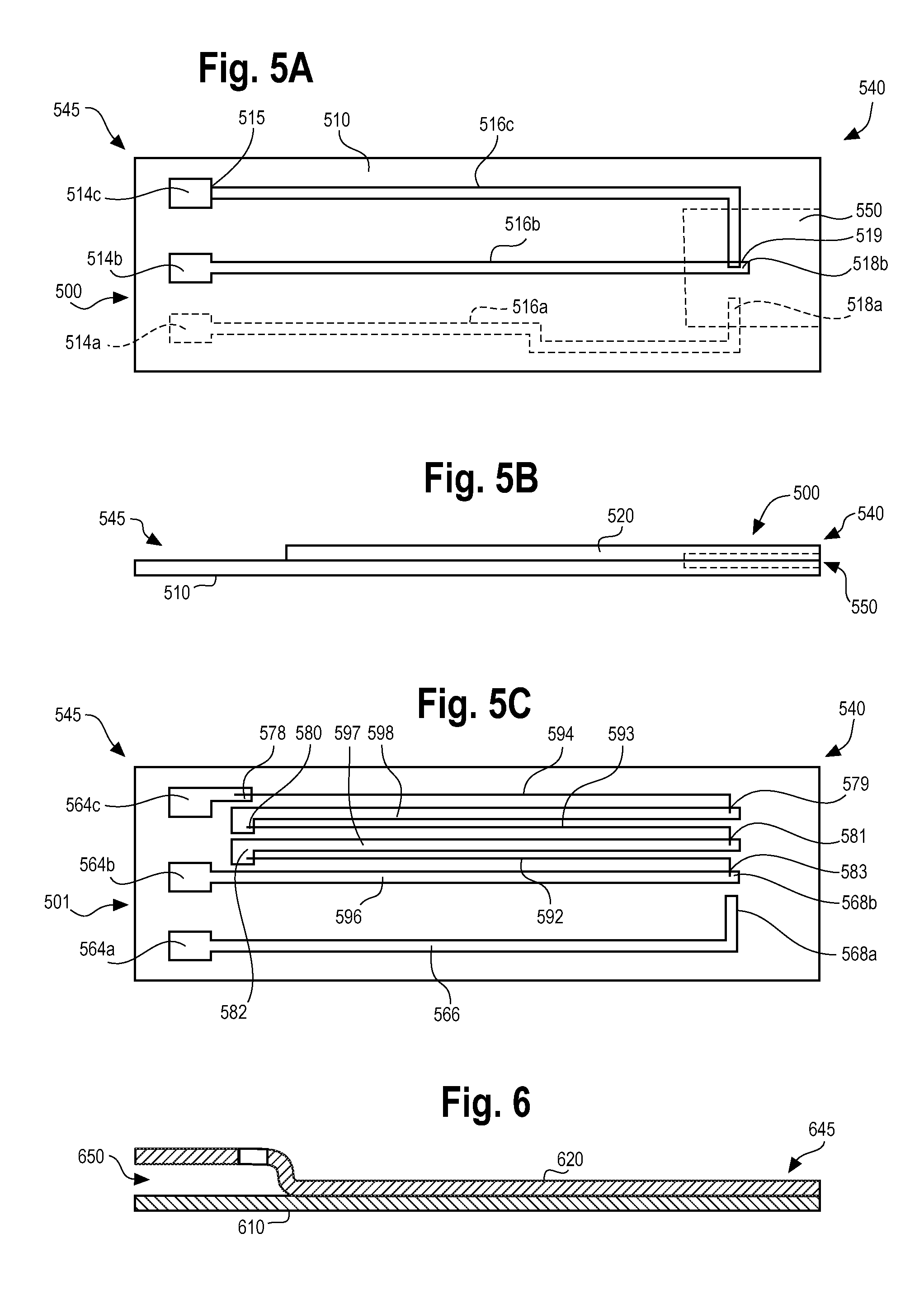
[0005]According to one embodiment, a test sensor configured to determine a fluid analyte concentration of a fluid sample includes a test sensor body, a first conductive trace, a second conductive trace, and a third conductive trace. The test sensor body includes a first region that has a fluid-receiving area, a second region that is separate from the first region, and a first temperature sensing interface that is disposed at or adjacent to the fluid-receiving area. The fluid-receiving area is configured to receive a fluid sample and allow the fluid sample to be analyzed to determine a fluid analyte concentration. The first conductive trace is disposed on the test sensor body, and at least a portion of the first conductive trace is disposed in the first region. The second conductive trace is disposed on the test sensor body. The third conductive trace is also disposed on the test sensor body. The third conductive trace extends from the first region to the second region. The third conductive trace is connected to the first conductive trace at the first temperature sensing interface. The third conductive trace includes a different material than the first conductive trace such that a first thermocouple is formed at the first temperature sensing interface. The first thermocouple provides temperature data to assist in determining the fluid analyte concentration.
[0011]According to another embodiment, a method for making a test sensor configured to determine a fluid analyte concentration of a fluid sample includes forming a first conductive trace on a test sensor body. The test sensor body includes a first region that has a fluid-receiving area, a second region that is separate from the first region, and a first temperature sensing interface that is disposed at or adjacent to the fluid-receiving area. The fluid-receiving area is configured to receive a fluid sample and allow the fluid sample to be analyzed to determine a fluid analyte concentration. At least a portion of the first conductive trace is disposed in the first region. The method further includes forming a second conductive trace on the test sensor body, and forming a third conductive trace on the test sensor body. The third conductive trace extends from the first region to the second region. The third conductive trace is connected to the first conductive trace at the first temperature sensing interface. The third conductive trace includes a different material than the first conductive trace such that a first thermocouple is formed at the first temperature sensing interface. The thermocouple provides temperature data to assist in determining the fluid analyte concentration.
[0012]According to another embodiment, a method for making a test sensor configured to determine a fluid analyte concentration of a fluid sample includes forming a metal layer on a substrate, attaching the substrate with the metal layer to a test sensor body, forming a first conductive trace on the metal layer, forming a second conductive trace on the metal layer, and forming a third conductive trace on the metal layer. The test sensor body includes a first region that has a fluid-receiving area, a second region that is separate from the first region, and a first temperature sensing interface that is disposed at or adjacent to the fluid-receiving area. The fluid-receiving area is configured to receive a fluid sample and allow the fluid sample to be analyzed to determine a fluid analyte concentration. At least a portion of the first conductive trace is disposed in the first region. The third conductive trace extends from the first region to the second region. The third conductive trace is connected to the first conductive trace at the first temperature sensing interface. The third conductive trace includes a different material than the first conductive trace such that a first thermocouple is formed at the first temperature sensing interface. The thermocouple provides temperature data to assist in determining the fluid analyte concentration.

Problems solved by technology

However, if the actual temperature of the reagent and the test sensor are different, the calculated blood glucose concentration decreases in accuracy.
An increase in temperature or the presence of a heat source within a blood glucose meter will generally result in erroneous blood glucose measurements.
Furthermore, the thermal properties of a blood glucose meter often render the system slow to respond to environmental changes such as a change in temperature.

Method used


Image

  • System and Apparatus for Determining Temperatures in a Fluid Analyte System
  • System and Apparatus for Determining Temperatures in a Fluid Analyte System
  • System and Apparatus for Determining Temperatures in a Fluid Analyte System

Examples


Embodiment Construction

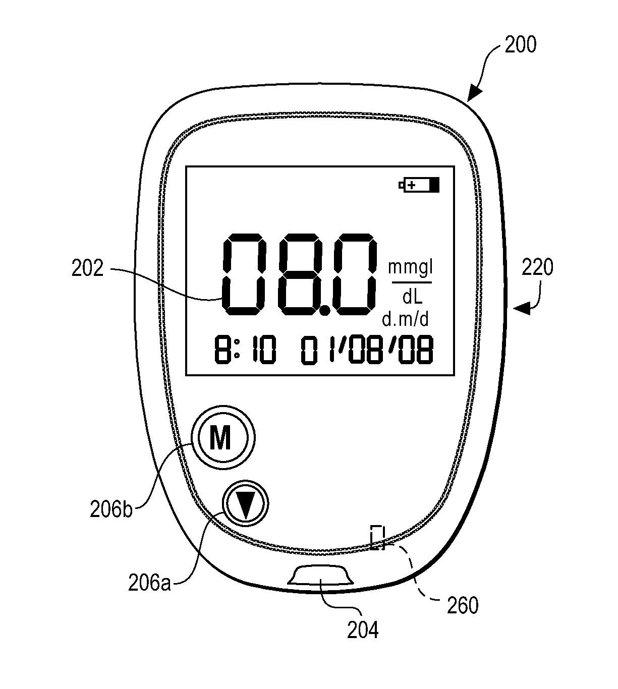
[0049]Generally, a test sensor is employed to collect a blood sample, and a blood glucose meter measures a reaction between the glucose in the sample with a reagent on the test sensor to calculate a corresponding blood glucose concentration. The temperature of the reagent affects the reaction between the glucose and the reagent. As such, the temperature of the reagent also affects the blood glucose concentration calculated by the blood glucose meter. The temperature of the reagent is assumed to be substantially equal to the ambient temperature in or surrounding the meter. Temperature sensing elements in the blood glucose meter can provide an estimate of the ambient temperature, which can then be used in the calculation of the blood glucose concentration. However, the blood glucose meter includes various heat-generating elements that can cause the temperature measured by the temperature sensing elements in the meter to differ from the ambient temperature. When the temperature measure...


PUM

PropertyMeasurementUnit
Temperatureaaaaaaaaaa
Concentrationaaaaaaaaaa
Electrical resistanceaaaaaaaaaa

Abstract

A test sensor includes a body, a first conductive trace, a second conductive trace, and a third conductive trace. The body includes a first region that has a fluid-receiving area, a second region separate from the first region, and a first temperature sensing interface disposed at or adjacent to the fluid-receiving area. The fluid-receiving area receives a sample. The first trace is disposed on the body, and at least a portion of the first trace is disposed in the first region. The second and third traces are disposed on the body. The third trace extends from the first to the second regions. The third trace is connected to the first trace at the first temperature sensing interface. The third trace includes a different material than the first trace. A first thermocouple is formed at the first temperature sensing interface. The thermocouple provides temperature data to determine an analyte concentration.

Description

CROSS-REFERENCE TO RELATED APPLICATIONS[0001]This application claims priority to and the benefit of U.S. Provisional Application No. 61 / 219,549, filed Jun. 23, 2009, which is hereby incorporated by reference herein in its entirety.FIELD OF THE INVENTION[0002]The present invention generally relates to fluid analyte systems, and more particularly, to the determination of differential temperatures in fluid analyte systems having one or more temperature sensing locations.BACKGROUND OF THE INVENTION[0003]The quantitative determination of analytes in body fluids is of great importance in the diagnoses and maintenance of certain physiological conditions. For example, lactate, cholesterol, and bilirubin should be monitored in certain individuals. In particular, determining glucose in body fluids is important to individuals with diabetes who must frequently check the glucose level in their blood to regulate the glucose intake in their diets. The results of such tests can be used to determine...

Claims


Application Information

Patent Timeline
IPC IPC(8): G01N25/00G01K7/02G01K7/16H05K3/10
CPCA61B5/01A61B5/14532A61B5/14546A61B5/1486G01K3/08Y10T29/49155G01K7/02G01K7/16G01K13/00G01N27/3274G01N27/26G01K7/01G01N33/48785G01N33/49G01N27/3272G01N27/308G01N27/4166
Inventor SUN, STEVE HOI-CHEONGCHINNAYELKA, SWETHACREAVEN, JOHN P.EDELBROCK, ANDREW J.HOLZER, MATTHEW B.PARASNIS, NARASINHA C.REYNOLDS, JEFFERY S.RIPLEY, PAUL M.CHARLTON, STEVEN C.WANG, XINWU, MU
Owner ASCENSIA DIABETES CARE HLDG AG
Learn More