Airless thermal regenerator or enhancer with mixer

a technology of airless thermal regenerator and mixer, which is applied in the direction of machines/engines, exhaust treatment electric control, transportation and packaging, etc., can solve the problems of difficult ignition, difficult to produce more hydrocarbons, disadvantageous traditional configuration, etc., and achieve the effect of reducing the size of the fuel droplet and improving the ignition

Inactive Publication Date: 2010-12-23
EMCON TECHNOLOGIES
View PDF8 Cites 20 Cited by
  • Summary
  • Abstract
  • Description
  • Claims
  • Application Information

AI Technical Summary

Benefits of technology

[0004]A component assembly includes a combustor that comprises a fuel-fired burner for a mobile application. In one example, the fuel-fired burner comprises one of a thermal regenerator or airless thermal enhancer operating with airless injection and which is configured to regenerate a particulate filter. A mixer is positioned within the thermal regenerator or enhancer to improve ignition by reducing fuel droplet size. A low pressure region is also created behind the mixer which further assists the ignition process.

Problems solved by technology

This traditional configuration is disadvantageous from a cost and complexity perspective.
However, airless TRs and TEs have significantly larger fuel droplet sizes, which are difficult to ignite and produce more hydrocarbons.

Method used


Image

  • Airless thermal regenerator or enhancer with mixer
  • Airless thermal regenerator or enhancer with mixer
  • Airless thermal regenerator or enhancer with mixer

Examples


Embodiment Construction

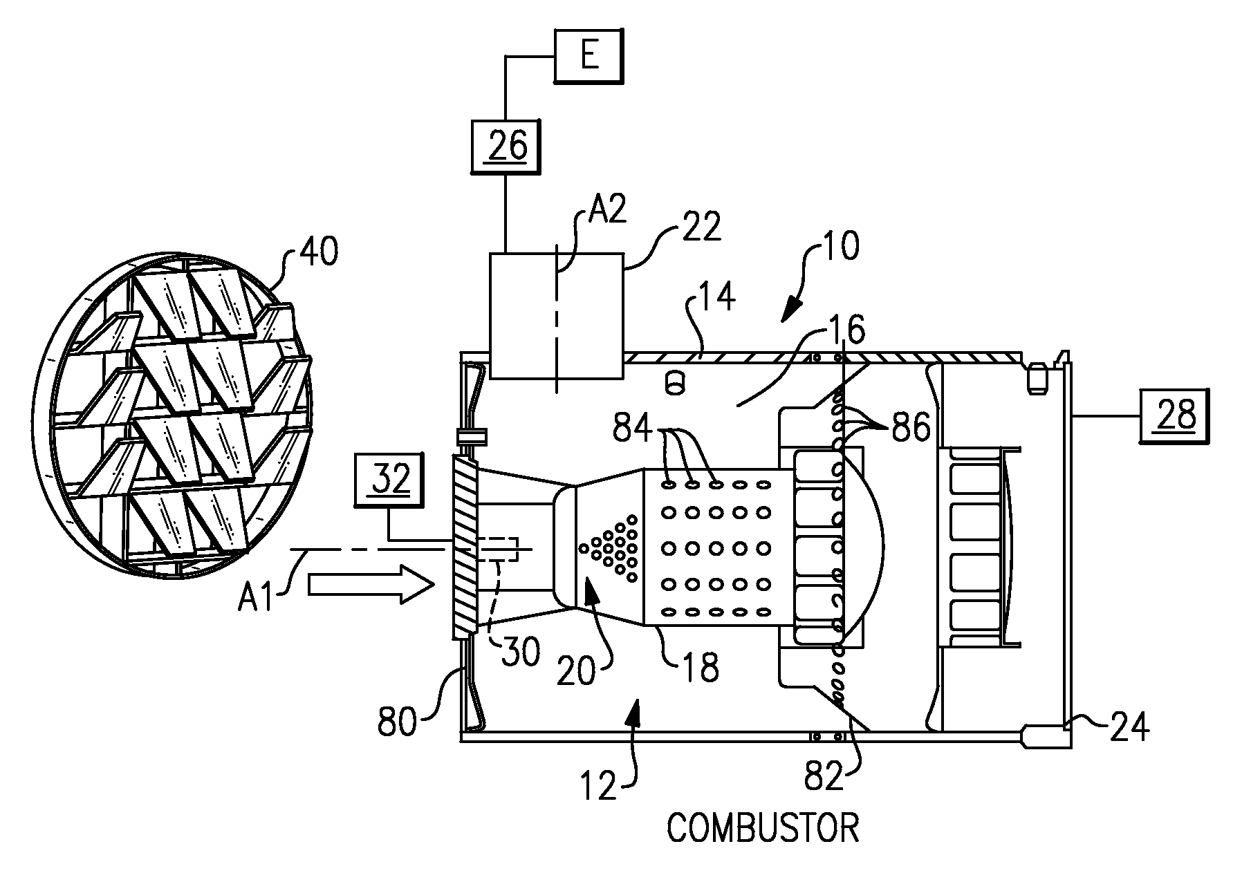
[0014]FIG. 1 shows an exhaust component assembly 10 with a combustor 12. The combustor 12 comprises any type of combustor where air-assisted fuel injection is replaced by airless injection. Examples of such combustors would include vehicle exhaust after treatment components, auxiliary vehicle passenger compartment heaters, turbine combustors, etc.

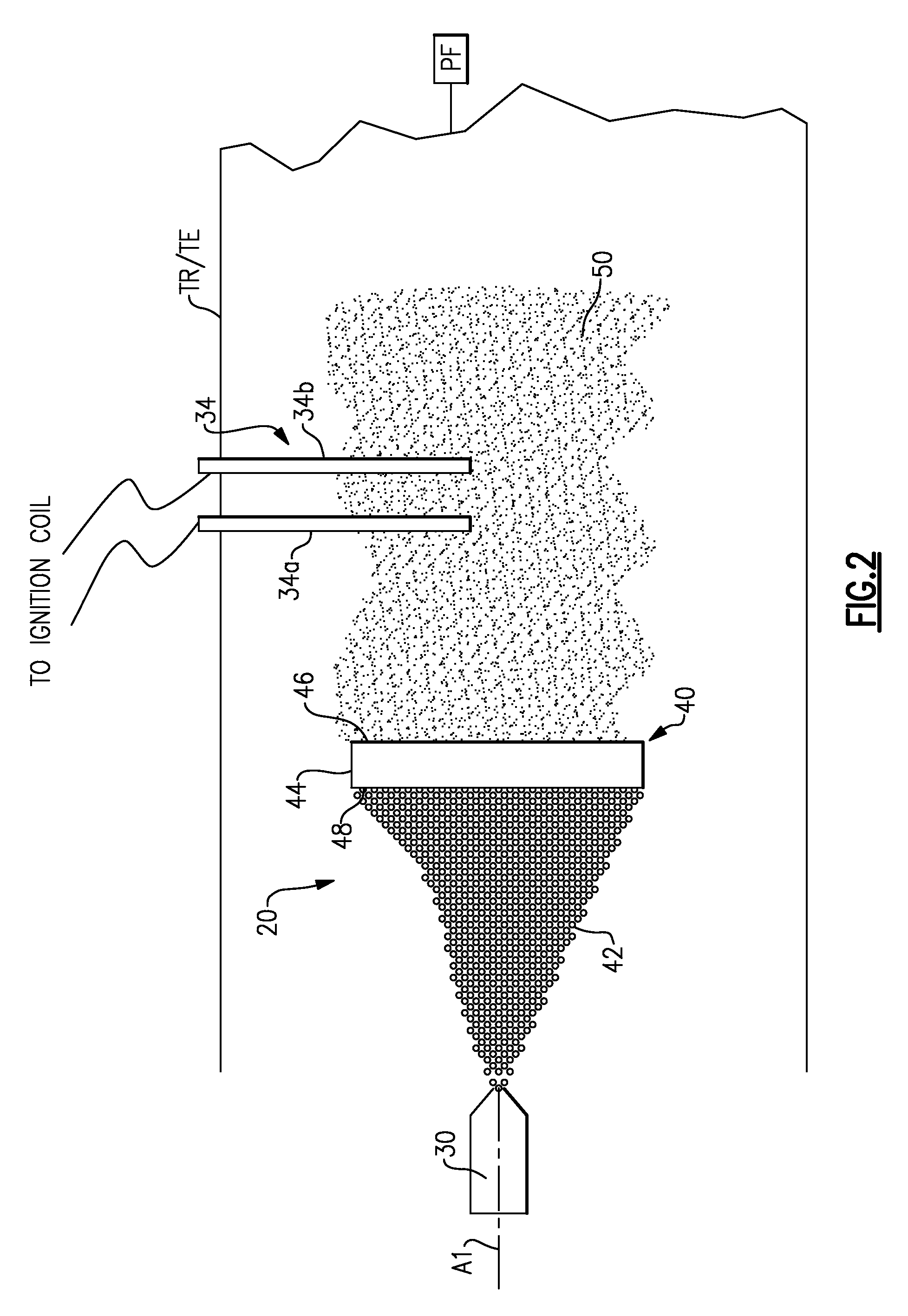
[0015]The exhaust component assembly 10 includes a housing 14 defining an internal cavity 16 and an internal wall structure 18 that defines a combustion chamber 20. The housing 14 includes an exhaust gas inlet 22 and an exhaust gas outlet 24. Exhaust gases generated from an engine E flows through any upstream exhaust components 26 to the exhaust gas inlet 22. Exhaust gases flow through the exhaust component assembly 10 to the exhaust gas outlet 24 and then on to downstream exhaust system components 28.

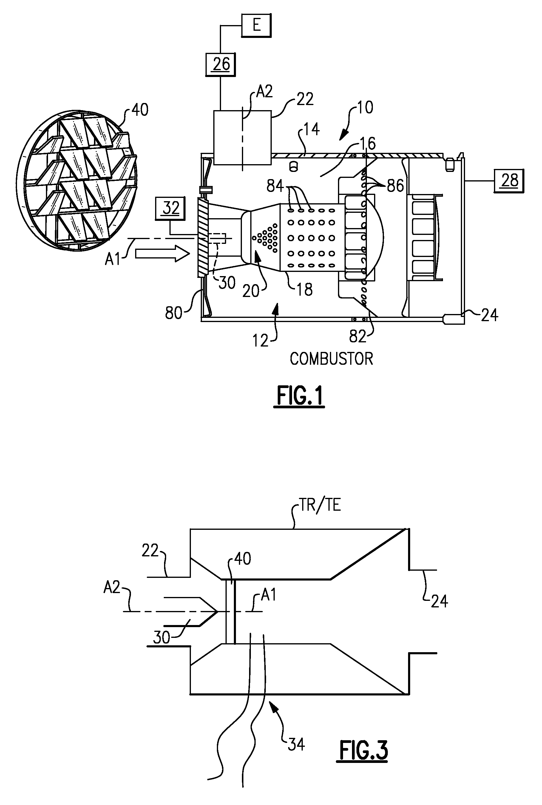
[0016]At least one fuel nozzle 30 is supported by the housing 14 to inject / spray fuel from a fuel supply 32 into the combustion chamber 20. T...


PUM


Abstract

A combustor comprises a fuel-fired burner for a vehicle application. In one example, the fuel-fired burner is configured to regenerate a particulate filter where the fuel-fired burner comprises one of a thermal regenerator or thermal enhancer that operates with airless fuel injection. A fuel nozzle supplies fuel to the fuel-fired burner and an igniter ignites fuel sprayed from the fuel nozzle. A mixer is positioned downstream of the fuel nozzle and upstream of the igniter and operates to reduce fuel droplet size, which improves ignition.

Description

TECHNICAL FIELD[0001]The subject invention relates to a fuel-fired burner for a mobile application, and more particularly to a vehicle exhaust system utilizing a thermal regenerator or enhancer that has a mixer.BACKGROUND OF THE INVENTION[0002]Exhaust systems are widely known and used with combustion engines. Some exhaust systems utilize a thermal regenerator (TR) or a thermal enhancer (TE). A TR is an active unit that enables regeneration of a diesel particulate filter (DPF) as well as providing exhaust thermal management under various operating conditions. A TE is a partial range burner supporting active DPF regeneration or exhaust thermal management. The TE elevates the exhaust temperature of exhaust gas to enable regeneration of a DPF under low temperature conditions or to improve the efficiency of NOx reduction catalysts.[0003]The TR and TE include a combustor unit that includes an air supply line, a fuel supply line and an igniter unit. This traditional configuration is disadv...

Claims


Application Information

Patent Timeline
IPC IPC(8): F01N3/023F01N3/035F01N3/10
CPCB01F5/0603B01F5/0608B01F5/0616B01F5/0643F01N2240/20B01F5/0693F01N3/0256F01N3/36F01N9/002B01F5/0682Y02A50/20B01F25/421B01F25/4233B01F25/4315B01F25/4322B01F25/4523B01F25/45
Inventor KHADIYA, NAVIN
Owner EMCON TECHNOLOGIES
Why Eureka
Try Eureka