Air hybrid vehicle

Inactive Publication Date: 2010-12-16
MA INNOVATIONS 2T4LTD
View PDF9 Cites 46 Cited by
  • Summary
  • Abstract
  • Description
  • Claims
  • Application Information

AI Technical Summary

Benefits of technology

[0007]The vehicle of the invention achieves fuel saving and high performance by boost substitution. By this it is meant that the engine is boosted with boost air which has been produced and stored using energy that would otherwise have been wasted during vehicle braking, instead of with boost air produced by an engine driven supercharger or an exhaust driven turbocharger both of which would have required fuel to be burnt in the engine in order to generate the boost air at the equivalent pressure. Thus by boost substitution, this fuel is saved by not loading the engine with any supercharger or turbocharger when the required boost air is supplied to the engine from the boost air storage tank.
[0042]The present invention is applicable to any vehicle powered by a spark ignition or compression ignition engine with or without an air charger. Compared with a non-hybrid vehicle powered by a similar engine, the present invention converts it to a high efficiency boost-air hybrid vehicle with only a few additional components at low technology and low cost and there is no adverse effect on the performance and driveability of the vehicle while the energy balance is shifted substantially towards better fuel economy.

Problems solved by technology

Compared with boost air, using pneumatic air for boosting the engine is the root cause of many inefficiencies: first the compression losses incurred when producing and storing the compressed air at the higher pressure and temperature, then the expansion losses incurred when releasing the high pressure air back to boost air pressure, both of which losses are totally unnecessary and wasteful when only boost air is required.

Method used


Image

  • Air hybrid vehicle
  • Air hybrid vehicle
  • Air hybrid vehicle

Examples


Embodiment Construction

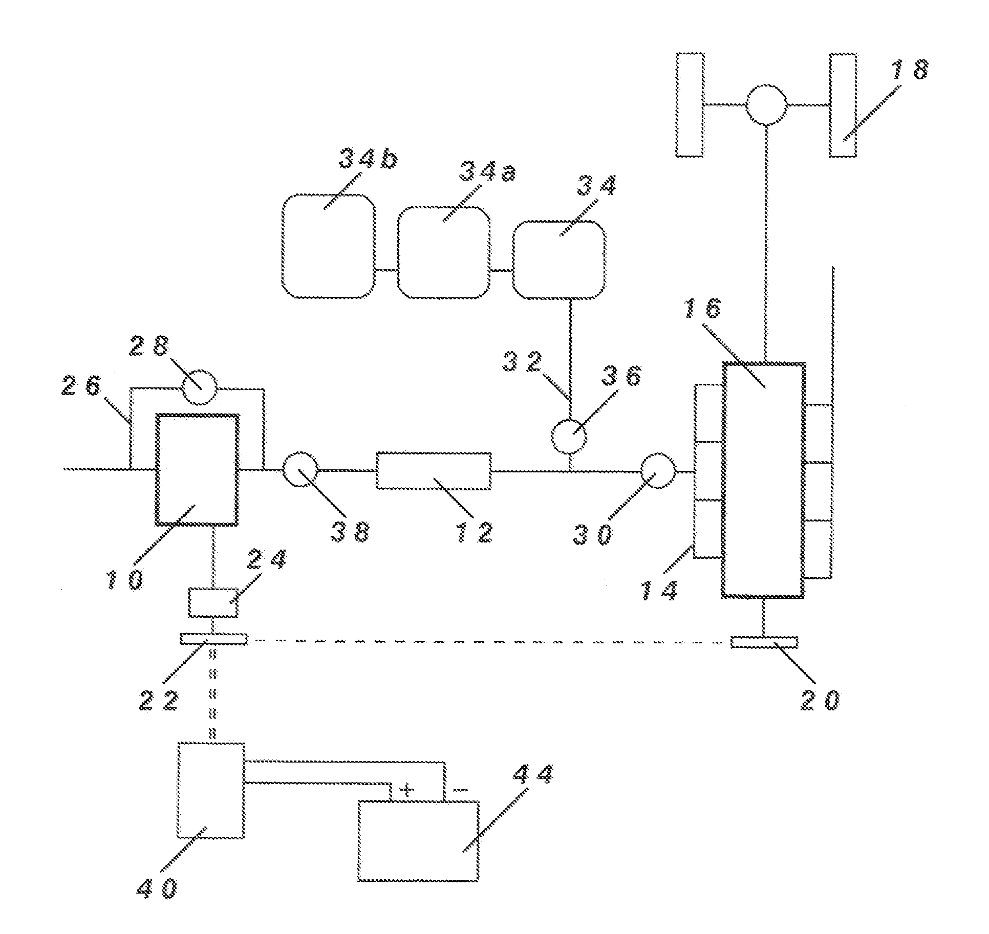
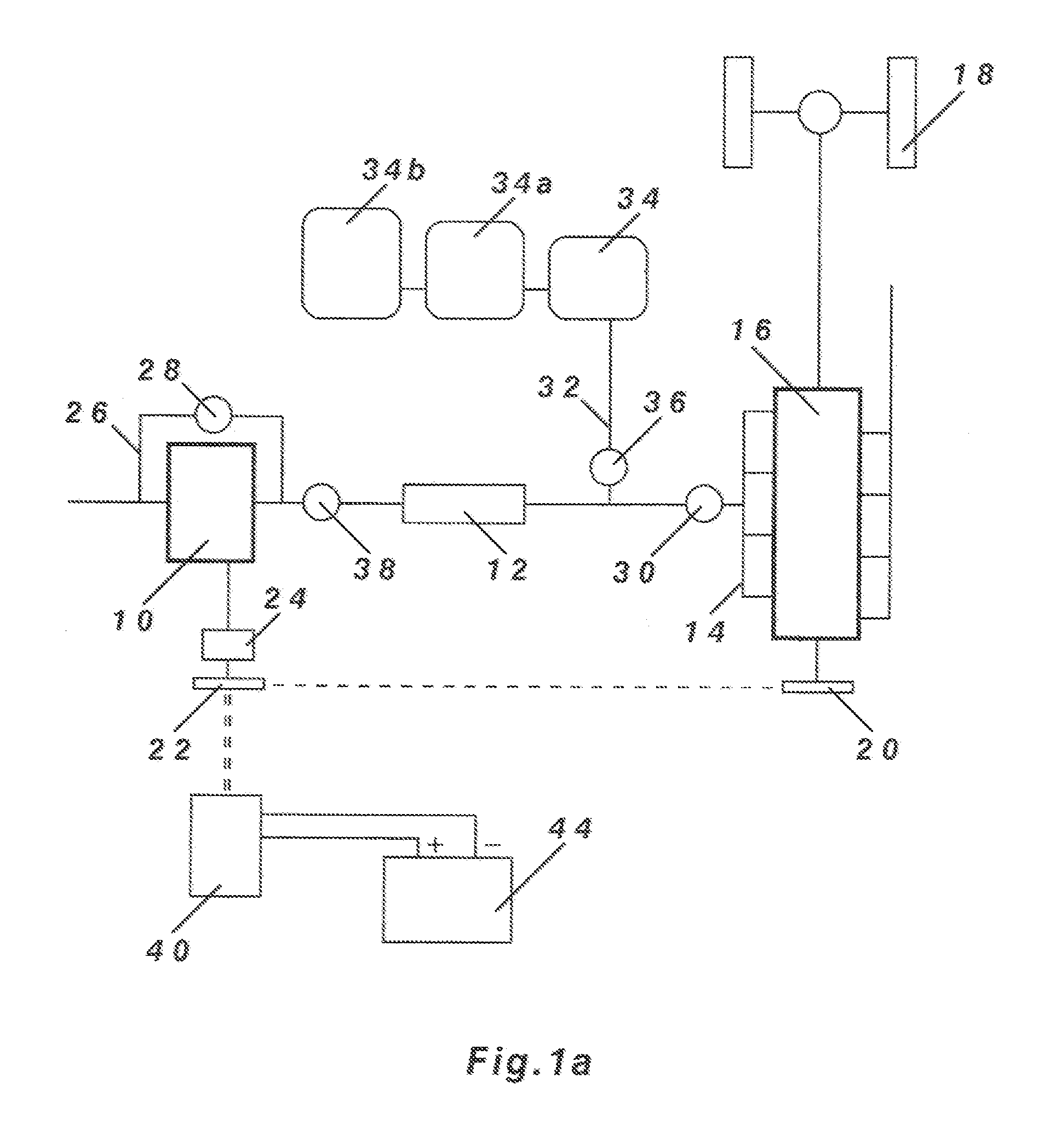
[0048]FIG. 1a shows an internal combustion engine 16 driving the wheels 18 of a road vehicle. The engine 16 is equipped with a supercharger 10 supplying boost air to the engine via an intercooler 12 and intake manifold 14. The supercharger 10 may be driven by the engine from a pulley 20 in the engine to a pulley 22 in the supercharger as shown by the single dashed line. The pulley 22 may be a clutch pulley which can be engaged or disengaged at any time on demand. Alternatively, the supercharger 10 may be driven by an electric motor 40 as shown by the double dashed line. A variable speed ratio drive 24 is also shown for driving the supercharger 10 at an optimum speed ratio with the engine.

[0049]The supercharger 10 has an air bypass system comprising a bypass connection 26 between the entry and the exit of the supercharger 10 controlled by a bypass valve 28. When boost is required, the bypass valve 28 is closed and the supercharger 10 is driven on load to produce boost air delivered t...


PUM


Abstract

An air hybrid vehicle is described powered by an internal combustion engine (16) which may or may not be equipped with a supercharger or turbocharger (10) for boosting the engine (16). In the invention, power is taken from the vehicle to drive the engine (16) during deceleration or coasting of the vehicle. The engine (16) absorbs kinetic energy from the vehicle and uses that energy to produce boost air which is transferred and stored in a boost air storage tank (34) on board the vehicle at a storage pressure not exceeding 3 bar absolute pressure. The vehicle achieves fuel saving and high performance by boost substitution when this boost air is used to supply the engine (16) for short periods during acceleration or cruising of the vehicle without relying on any air charger, temporarily fulfilling the role of an air charger without actually driving an air charger by substituting the boost normally supplied by an air charger with an equivalent boost produced and stored during regenerative braking. To accommodate a large boost air storage tank (34), the body of the vehicle is adapted with air-tight volumes linked together to form one large storage volume.

Description

FIELD OF THE INVENTION[0001]The present invention relates to a hybrid vehicle in which energy that would otherwise be wasted during braking is stored for subsequent re-use in the form of pressurised air. The concept of re-using energy recovered while braking a vehicle is often referred to as regenerative braking.BACKGROUND OF THE INVENTION[0002]It is known that a regenerative hybrid vehicle can achieve significant reduction in fuel consumption and CO2 emissions by recovering some of the kinetic energy of the vehicle during deceleration or braking of the vehicle and transforming it into another form of energy which can be stored and later re-used.[0003]One example is the electric hybrid vehicle in which the braking energy is transformed into electric energy and stored in an electric battery for future use. Another example is the inertia hybrid vehicle in which the braking energy is transformed into inertial energy and stored in a spinning flywheel for future use. A further example is...

Claims


Application Information

Patent Timeline
IPC IPC(8): B60K6/12B60W20/00
CPCB60K6/12Y02T10/6282B60W10/184B60W10/30B60W20/00B60W30/18127B60Y2400/15F02B21/00F02B29/00F02B33/44F02B37/16F02B39/04F02B39/12F02D41/0007F02D41/12Y02T10/146Y02T10/148Y02T10/6208Y02T10/6269Y02T10/144B60Y2400/435B60W20/13B60W10/06Y02T10/12Y02T10/62B60K13/02F02D23/00F02M26/09F02D23/005F02D21/08F02B11/02F02M26/00F02D17/00B60K6/20
Inventor MA, THOMAS TSOI-HEI
Owner MA INNOVATIONS 2T4LTD
Why Eureka
Try Eureka