Highly corrosion-resistant member and manufacturing process for the same

Inactive Publication Date: 2010-12-16
JTEKT CORP +1
View PDF12 Cites 115 Cited by
  • Summary
  • Abstract
  • Description
  • Claims
  • Application Information

AI Technical Summary

Benefits of technology

[0020]In accordance with the highly corrosion-resistant members according to the present invention and the manufacturing processes for the same, the surface of the substrate made of stainless steel is not exposed to high temperatures (>450° C.). Consequently, the corrosion resistance of the substrate is kept equivalent to the corrosion resistance of the original stainless steel that has not been exposed to any high temperature. Specifically, the highly corrosion-resistant members according to the present invention are good in terms of corrosion resistance. Note that, since an inner temperature of the substrate usually becomes lower than the surface temperature of the substrate, highly corrosion-resistant members having desirable corrosion resistance are obtainable in the present invention unless at least the surface of the substrate is exposed to the high temperatures.
[0021]It is possible to secure the adhesiveness between the substrate and the amorphous carbon film by forming the intermediate layer on at least a part of the surface of the substrate, without ever performing any nitriding treatment to the substrate. In a substrate which is not subjected to any nitriding treatment, nitrogen atoms do not diffuse / infiltrate so that no internal stress generates in the superficial-layer portion, and thereby the lowering in the corrosion resistance of the substrate is suppressed.
[0022]Moreover, by means of performing nitriding treatment onto the substrate at low temperatures (450° C. or less), the substrate is not exposed under the high temperatures, and additionally the generation of internal stress at the surface of the substrate is reduced. Consequently, the corrosion resistance of the substrate is kept equivalent to the corrosion resistance of the original stainless steel. This is because the nitriding treatment is carried out at the low temperatures and thereby the internal stress, which is generated by nitrogen atoms that diffuse and then infiltrate, becomes small.

Problems solved by technology

In general, in metallic materials, corrosion becomes likely to occur under the conditions that bending stresses or tensile stresses are applied to them.
Therefore, the surface of substrate also has a tendency to be likely to corrode because of the cause that the internal stress generates in the superficial-layer portion of stainless steel by means of nitriding.
As a result, the stainless steel becomes likely to corrode (i.e., sensitization).

Method used


Image

  • Highly corrosion-resistant member and manufacturing process for the same
  • Highly corrosion-resistant member and manufacturing process for the same
  • Highly corrosion-resistant member and manufacturing process for the same

Examples


embodiment

[0057]Next, the present invention will be explained in more detail while naming a specific embodiment.

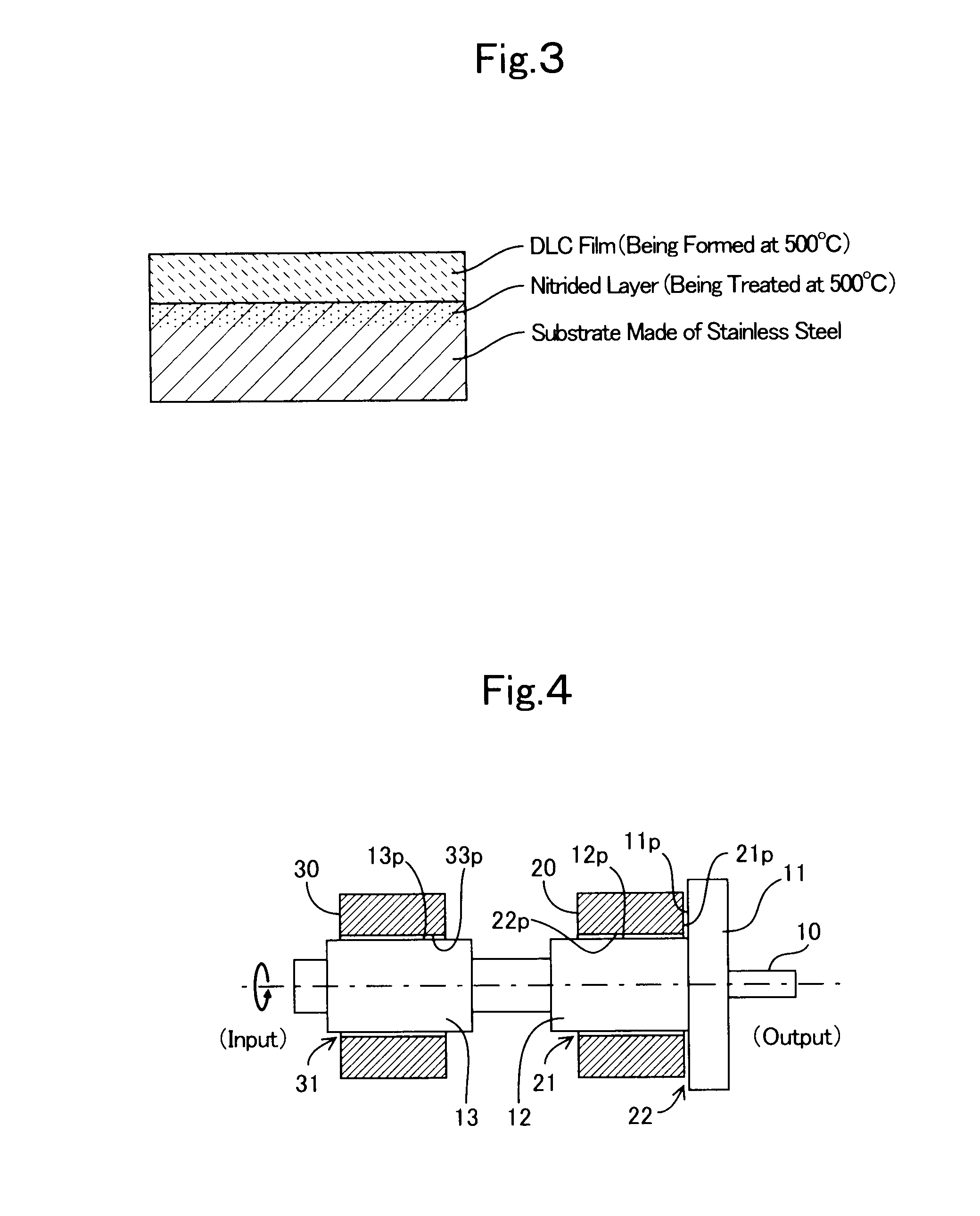
[0058]In an embodiment and a comparative example that will be explained hereinafter, a driving shaft in a bearing-structured section of water pump was made. The bearing-structured section of water pump is illustrated in FIG. 4.

[0059]The bearing-structured section of water pump is equipped with a pump shaft 10 (i.e., a driving shaft), and bearing metals 20 and 30 that support the pump shaft 10 rotatably.

[0060]The pump shaft 10 possesses: a disk-shaped flange portion that extends in the axially central direction; a first major-diameter portion 12 that neighbors the flange portion 11; and a second major-diameter portion 13 that is placed with an intervening space between itself and the first major-diameter portion 12; in this order from the output side. Both of the bearing metals 20 and 30 are shaped cylindrically, and the major-diameter portion 12 and second major-diameter portion 13 ...

embodiment no.1

Embodiment No. 1

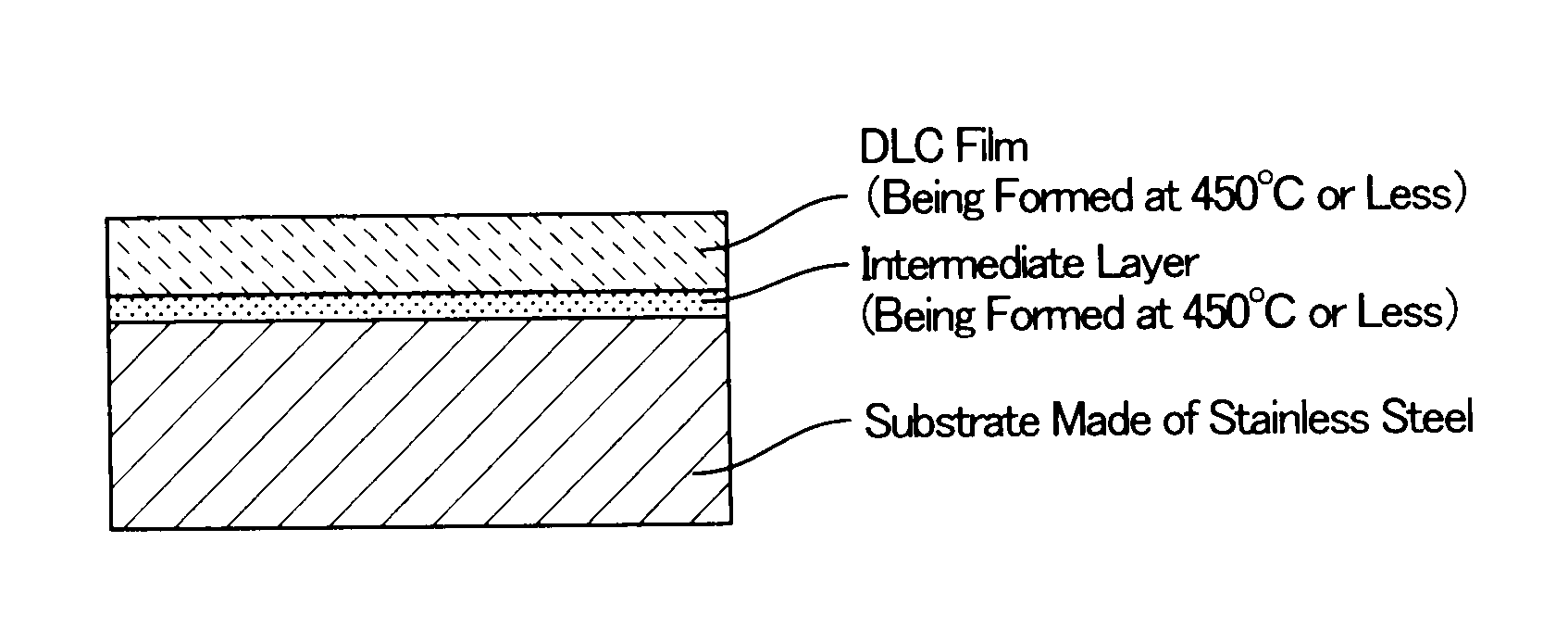
[0062]In the present embodiment, a titanium film (intermediate layer) and a DLC film were formed onto the outer peripheral surface of the substrate by the following procedures, thereby making the pump shaft 10 shown in FIG. 4.

[0063]Note that, for the formations of the titanium film and DLC film, a PIG-type plasma CVD apparatus that was produced by SHINKOH SEIKI Co., Ltd. (“APIG-1060D,” hereinafter abbreviated to as “PIG”) was used. The PIG apparatus had a plasma source that comprised a hot-cathode filament and an anode. A raw-material gas that was introduced into the apparatus was decomposed and then dissociated by means of plasma that was generated at the plasma source, and was thereby turned into a film onto a substrate's surface (i.e., a hot-cathode PIG plasma CVD method). Moreover, since a sputtering cathode that was connected with a direct-current electric source is disposed within this PIG apparatus, a film forming by means of direct-current sputtering method w...


PUM

PropertyMeasurementUnit
Temperatureaaaaaaaaaa
Electrical resistanceaaaaaaaaaa

Abstract

A highly corrosion-resistant member that is equipped with: a substrate made of stainless steel; an intermediate layer coated on at least a part of a surface of the substrate; and an amorphous carbon film coated on at least a part of a surface of the intermediate layer is completed by forming the intermediate layer and amorphous carbon film at such a low temperature that a temperature of the surface of the substrate is 450° C. or less. Another highly corrosion-resistant member that is equipped with: a substrate made of stainless steel, substrate whose superficial-layer portion is subjected to nitriding treatment; and an amorphous carbon film coated on at least a part of a surface of the superficial-layer portion is completed by carrying out the nitriding treatment and a formation of the amorphous carbon film at such a low temperature that a temperature of a surface of said substrate is 450° C. or less.In the aforementioned highly corrosion-resistant members, the surface of the substrate that is made of stainless steel is not exposed to high temperatures (>450° C.). Consequently, the corrosion resistance of the substrate is kept equivalent to the corrosion resistance of the original stainless steel that has not been exposed to any high temperature.

Description

TECHNICAL FIELD[0001]The present invention relates to a highly corrosion-resistant member that exhibits high corrosion resistance even when being employed in circumstances where corrosion is likely to occur, and to a manufacturing process for the same.BACKGROUND ART[0002]Amorphous carbon (diamond-like carbon: DLC) having an amorphous structure is good in terms of mechanical characteristics, such as wear resistance and solid lubricating property, and possesses corrosion resistance, insulating property, visible light / infrared light transmissivity, oxygen barrier property, and the like, simultaneously. Accordingly, it has been often the case that an amorphous carbon film is coated onto a substrate's surface and is then used as a protective film. For example, in Patent Literature No. 1, a water-lubrication bearing is disclosed, water-lubrication bearing which moves slidably while adapting water into a lubricant liquid. The water-lubrication bearing is equipped with a rotary-side member ...

Claims


Application Information

Patent Timeline
IPC IPC(8): C23C8/26B32B15/18B05D1/36C23C16/00
CPCC23C8/26C23C8/80C23C14/024C23C14/0605C23C16/0272C23C16/26F16C33/12F16C33/14F16C33/16C23C28/044C23C28/046C23C28/322C23C28/343C23C28/347F16C2206/04Y10T428/31678F16C33/122Y10T428/12625F16C2223/14F16C2223/60
Inventor SAITO, TOSHIYUKISUZUKI, MASAHIROHASHITOMI, HIROYUKI
Owner JTEKT CORP
Why Eureka
Try Eureka