
Snow removal vehicle

a road vehicle and snow technology, applied in snow cleaning, way cleaning, construction, etc., can solve the problems of ineffective vehicle function, inability to displace reserves, and insufficient melting systems, so as to reduce the amount of equipment

Inactive Publication Date: 2010-12-16
TRUBIANO ANTOINE
View PDF13 Cites 33 Cited by
  • Summary
  • Abstract
  • Description
  • Claims
  • Application Information

AI Technical Summary

Benefits of technology

[0006]Another feature of the present invention is to provide a snow removal vehicle which utilizes a single operator for its operation and reduces the amount of equipment normally required to clear snow from roads.

Problems solved by technology

A disadvantage of these is that the reservoirs are not displaceable and they are usually positioned in areas where large parking areas need to be maintained clear of snow.
However, such snow melting systems have not been found satisfactory as they are too small and the conduit will clog up with snow rendering the vehicle's function ineffective.
For snow removal applications on streets, such a vehicle is not practical.
Also, there are insufficient heating means to melt the snow faster than it is discharged within the chamber.
A snow blower is used to feed snow into a feeder chute which is of very long length and which obviously would clog up with snow rendering the entire vehicle ineffective.
This system is deemed to be inoperable because of its many deficiencies.
Further, the melting hopper is too small and would prevent the vehicle from operating at convenient speeds.

Method used


Image

  • Snow removal vehicle
  • Snow removal vehicle
  • Snow removal vehicle

Examples


Embodiment Construction

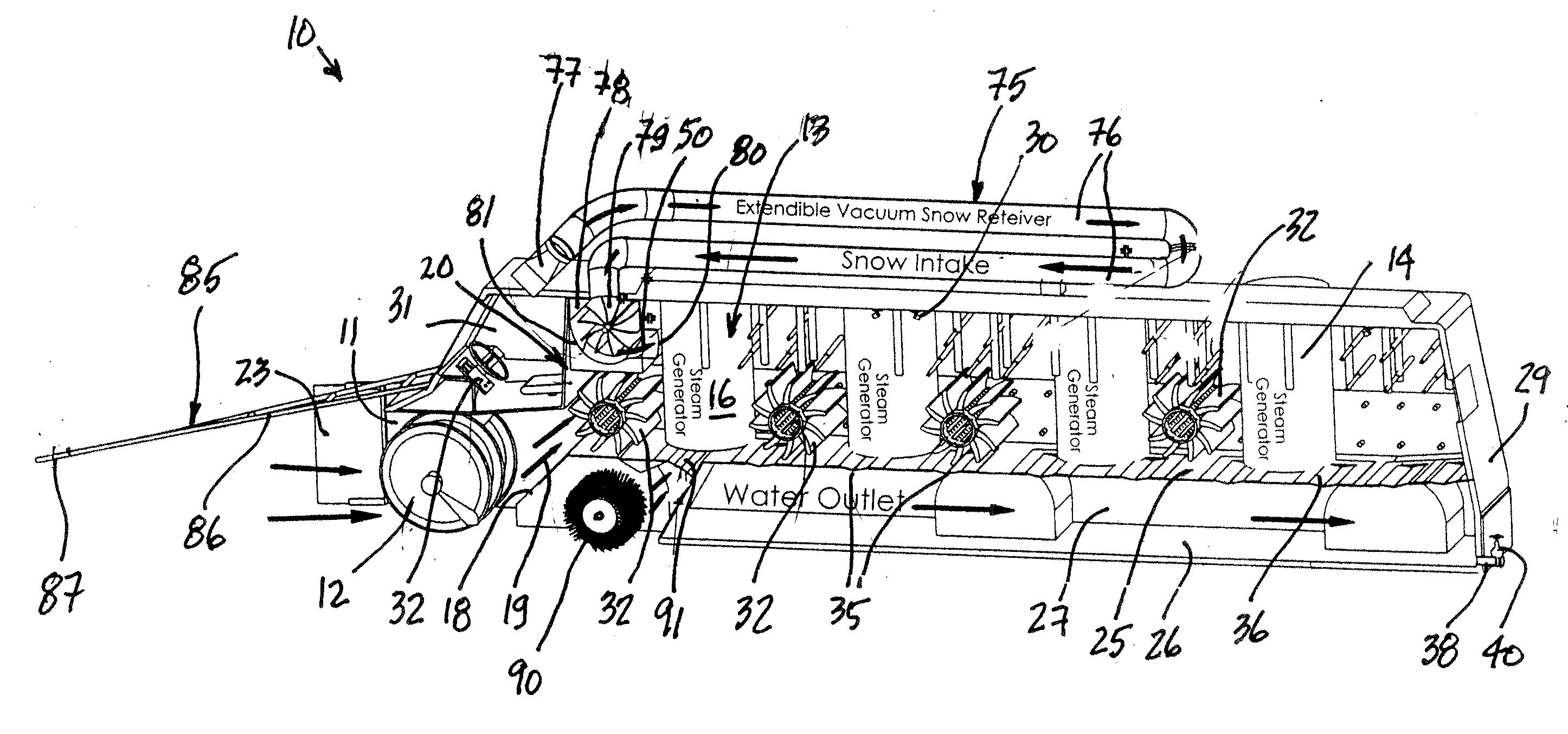
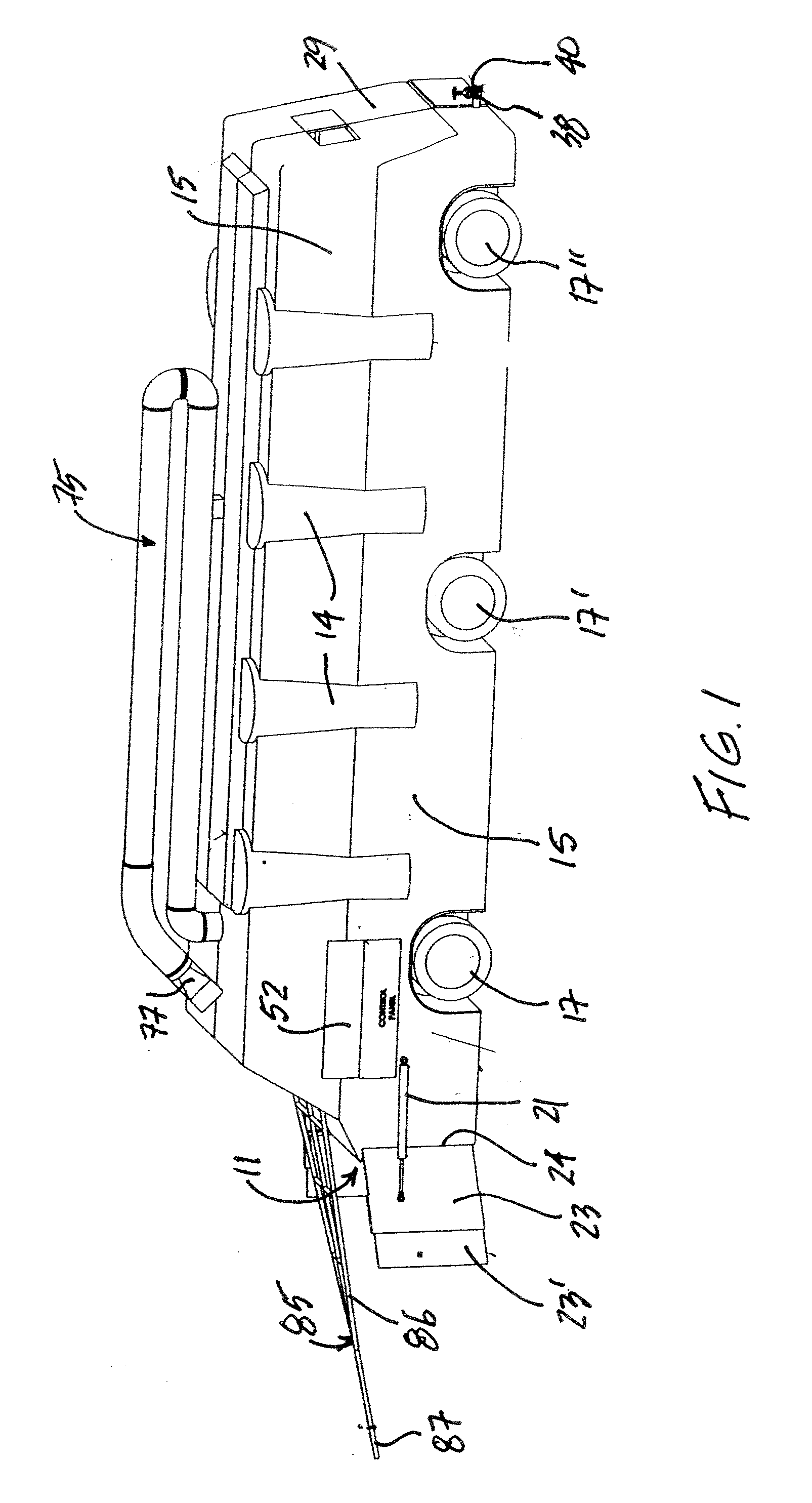
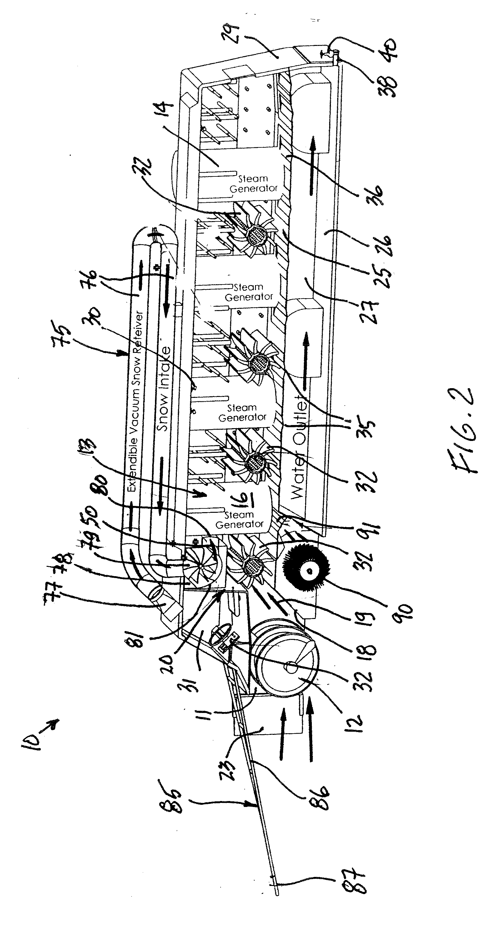
[0026]Referring to the drawings and more particularly to FIGS. 1 and 2, there is shown generally at 10 the snow removal vehicle of the present invention. As shown in FIGS. 1 and 2, the front end of the vehicle has a front entry opening 11 in which an auger means in the form of an auger screw 12 is mounted and driven at high speed whereby to eject snow positioned thereagainst rearwardly into the vehicle body 13. A plurality of steam generators 14 are mounted integral with the side walls 15 of the vehicle body 13. The vehicle body 13 defines therein an enclosed snow melting chamber 16 as shown in FIG. 2 and it communicates with the front entry opening 11. The vehicle body is also insulated. The vehicle 10 is supported on three sets of wheels 17, 17′ and 17″, but could also be supported on tracks or other propelling means, not shown.

[0027]As shown in FIG. 2, the front entry opening 11 is provided with a snow guiding ramp 18 rearwardly of the snow auger screw 12 whereby to guide project...


PUM


Abstract

A snow removal vehicle is described and it has an enclosed snow melting chamber provided with a plurality of high pressure steam jets which are connected to one or more steam generators. The enclosed snow melting chamber has a water collecting reservoir in a lower portion thereof below a bottom wall of the snow melting chamber. The bottom wall has passages to channel water from the snow melting chamber to the water collecting reservoir. The vehicle body has a front entry opening communicating with the snow melting chamber and an auger screw is mounted in the front entry opening to eject snow inside a forward end of the snow melting chamber. Snow propelling wheels are secured along at least a front end portion of the snow melting chamber to propel snow ejected from the auger along the snow melting chamber for contact by the high pressure steam to melt the snow. An outlet evacuating valve is provided to evacuate water collected in the water collecting reservoir. The vehicle may also be equipped with a hopper shute for use in a stationary mode to melt snow dumped in the shute.

Description

TECHNICAL FIELD[0001]The present invention relates to a snow removal road vehicle using high pressure steam jets to melt the snow inside an enclosed snow melting chamber of the vehicle.BACKGROUND ART[0002]Snow removal vehicles or containers are known wherein snow is collected and dumped into a container which is provided with conduits through which hot gases flow and which are located close to a top end of these containers whereby snow positioned thereon will melt and the water accumulate at the bottom of the container. Baffle plates are provided so that only water can percolate down into the reservoir. A disadvantage of these is that the reservoirs are not displaceable and they are usually positioned in areas where large parking areas need to be maintained clear of snow. Snow removal vehicles with articulated buckets are required to transport the snow to the container. The container usually has a conduit which connects to the city sewer system to discharge water therefrom.[0003]Wit...

Claims


Application Information

Patent Timeline
Patent Type & Authority Applications(United States)
IPC IPC(8): E01H5/10
CPCE01H5/104
Inventor TRUBIANO, ANTOINE
Owner TRUBIANO ANTOINE
Learn More