Method and amplifying stage for suppressing modulation distortion rate sensing errors in a resonator fiber optic gyroscope

a fiber optic gyroscope and modulation distortion technology, applied in the field of electromechanical gyroscopes, can solve the problems of reducing the accuracy of the rfog, reducing the performance of the rfog, and little improvement of the rfog performance, so as to reduce the total harmonic distortion of the rfog and suppress the 2nd order harmonic distortion

Active Publication Date: 2010-12-09
HONEYWELL INT INC
View PDF3 Cites 2 Cited by
  • Summary
  • Abstract
  • Description
  • Claims
  • Application Information

AI Technical Summary

Benefits of technology

[0008]A device and a method for suppressing 2nd order harmonic distortion in a Resonator Fiber Optic Gyroscope includes driving a laser to generate at least one of a plurality of counter propagating laser beams traveling through a fiber optic resonator according to a modulated signal. The modulated signal can be represented by a polynomial having two terms, and each of the two terms is suitably multiplied by a coefficient and a constant. A modulation amplitude adjuster amplifies the modulation signal by an amplification factor as it is used to drive the laser. When the amplification factor is suitably chosen to represent a square root of a ratio of the constants, the total harmonic distortion in the RFOG is minimized.

Problems solved by technology

However, rotation sensing errors associated with harmonic distortion most prevalent in 2nd order harmonics of the resonance frequency are simply amplified at the greater sensitivity, doing little to improve the performance of the RFOG.
This apparent asymmetry diminishes the accuracy of the RFOG by shifting the measured center frequency of the resonator.
Because the difference between the clockwise and counter-clockwise resonance frequencies are the measure of the rotational acceleration in an RFOG, the presence of the 2nd order harmonic degrades the performance of the RFOG.

Method used


Image

  • Method and amplifying stage for suppressing modulation distortion rate sensing errors in a resonator fiber optic gyroscope
  • Method and amplifying stage for suppressing modulation distortion rate sensing errors in a resonator fiber optic gyroscope
  • Method and amplifying stage for suppressing modulation distortion rate sensing errors in a resonator fiber optic gyroscope

Examples


Embodiment Construction

[0012]The following detailed description of the invention is merely exemplary in nature and is not to limit the invention or the application and uses of the invention. Furthermore, there is no intention to be bound by any theory presented in the preceding background of the invention or the following detailed description of the invention.

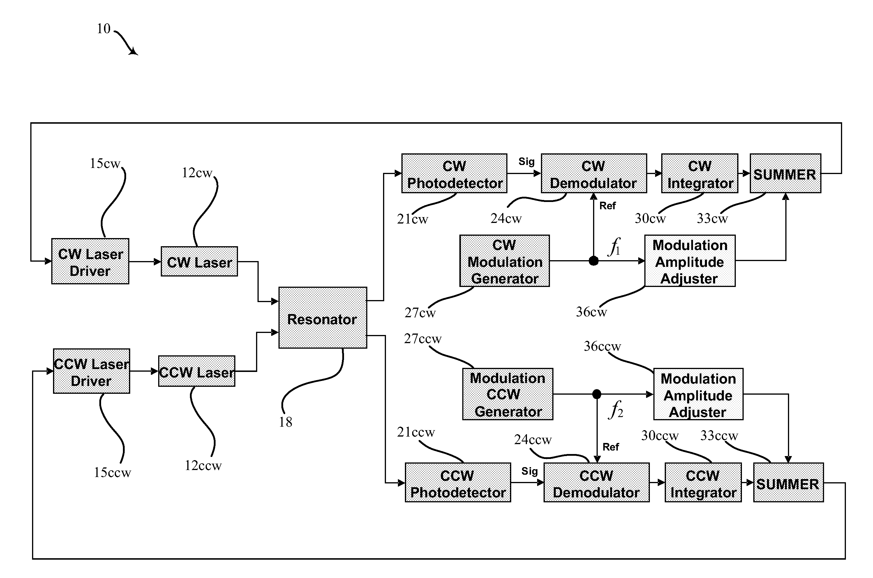
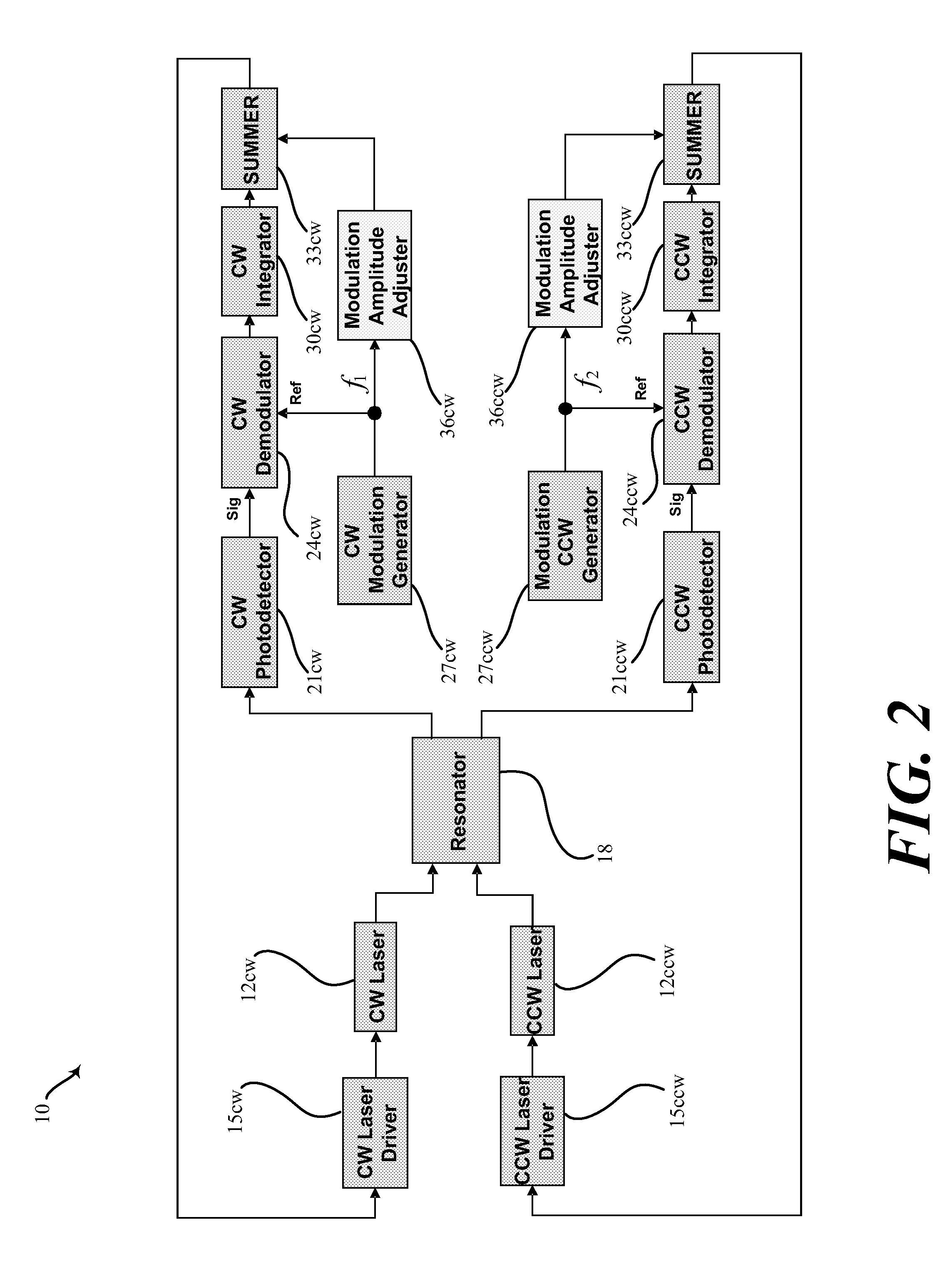
[0013]Referring now to the drawings, FIG. 2 is a schematic diagram of a resonator fiber optic gyro (RFOG) 10 in accordance with an exemplary embodiment of the present invention. The RFOG 10 includes each of a pair of lasers 12cw and 12ccw assigned respectively as the clockwise and counter clockwise light sources respectively, assigned thus to indicate the direction which the beam each generates will enter and travel through a fiber optic ring resonator 18. Each light beam emanates from the lasers 12cw and 12ccw, each has a frequency, and each is modulated at a frequency in accord with signals originating at each of a pair of laser drivers 15cw and 15...


PUM


Abstract

A device and a method for suppressing 2nd order harmonic distortion in a Resonator Fiber Optic Gyroscope includes driving a laser to generate at least one of a plurality of counter propagating laser beams traveling through a fiber optic resonator according to a modulated signal. The modulated signal can be represented by a polynomial having two terms, and each of the two terms is suitably multiplied by a coefficient and a constant. A modulation amplitude adjuster amplifies the modulation signal by an amplification factor as it is used to drive the laser. When the amplification factor is suitably chosen to represent a square root of a ratio of the constants, the total harmonic distortion in the RFOG is minimized.

Description

FIELD OF THE INVENTION[0001]This invention relates generally to electronic gyroscopes and, more specifically, to instrumentation for implementing electronic gyroscopes.BACKGROUND OF THE INVENTION[0002]Gyros have been used to measure rotation rates or changes in angular velocity about an axis of rotation. A basic conventional fiber optic gyro (FOG) includes a light source, a beam generating device, and a coil of optical fiber coupled to the beam generating device that encircles an area. The beam generating device transmits light beams into the coil that propagate in a clockwise (CW) direction and a counter-clockwise (CCW) direction along the core of the optical fiber. Many FOGs utilize glass-based optical fibers that conduct light along a solid glass core of the fiber. The two counter-propagating (e.g., CW and CCW) beams experience different pathlengths while propagating around a rotating closed optical path, and the difference in the two pathlengths is proportional to the rotational...

Claims


Application Information

Patent Timeline
Patent Type & Authority Applications(United States)
IPC IPC(8): G01C19/72
CPCG01C19/727
Inventor STRANDJORD, LEE K.
Owner HONEYWELL INT INC
Why Eureka
Try Eureka